Tag Archives: sumitomo gear motor

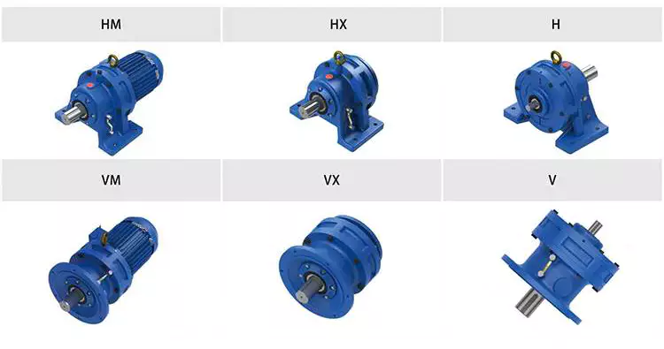
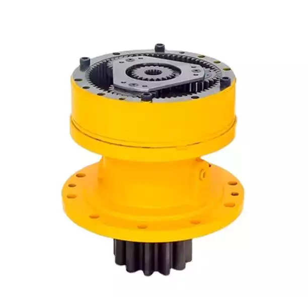
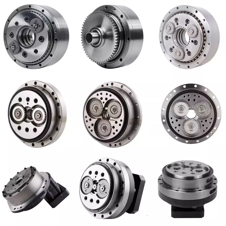
China Precision Cycloidal Cyclo Planetary Gear Motor Drive Sumitomo Reducer Gearbox China Manufacturer Industrial Wholesale cycloidal drive reducer

Product Description

Precision Cycloidal Cyclo Planetary Gear Motor Generate CZPT Reducer Gearbox China Maker Industrial Wholesale


/ Piece
|
100 Pieces

(Min. Order)

###

Application: Motor, Electric Cars, Motorcycle, Machinery, Marine, Agricultural Machinery, Car
Function: Distribution Power, Clutch, Change Drive Torque, Change Drive Direction, Speed Changing, Speed Reduction, Speed Increase
Layout: Coaxial
Hardness: Hardened Tooth Surface
Installation: Horizontal Type
Step: Three-Step

###

Samples:
US$ 9999/Piece
1 Piece(Min.Order)

|
Request Sample

Developing a Mathematical Model of a Cyclone Gearbox

Compared to planetary gearboxes, cycloidal gearboxes are often seen as the ideal choice for a wide range of applications. They feature compact designs that are often low friction and high reduction ratios.helical gearbox

Low friction

Developing a mathematical model of a cycloidal gearbox was a challenge. The model was able to show the effects of a variety of geometric parameters on contact stresses. It was able to model stiction in all quadrants. It was able to show a clear correlation between the results from simulation and real-world measurements.
The model is based on a new approach that enables modeling stiction in all quadrants of a gearbox. It is also able to display non-zero current at standstill. Combined with a good simulation algorithm, the model can be used to improve the dynamic behaviour of a controlled system.
A cycloidal gearbox is a compact actuator used for industrial automation. This type of gearbox provides high gear ratios, low wear, and good torsional stiffness. In addition, it has good shock load capacity.
The model is based on cycloidal discs that engage with pins on a stationary ring gear. The resulting friction function occurs when the rotor begins to rotate. It also occurs when the rotor reverses its rotation. The model has two curves, one for motor and one for generator mode.
The trochoidal profile on the cycloidal disc’s periphery is required for proper mating of the rotating parts. In addition, the profile should be defined accurately. This will allow an even distribution of contact forces.
The model was used to compare the relative performance of a cycloidal gearbox with that of an involute gearbox. This comparison indicates that the cycloidal gearbox can withstand more load than an involute gearbox. It is also able to last longer. It is also able to produce high gear ratios in a small space.
The model used is able to capture the exact geometry of the parts. It can also allow a better analysis of stresses.

Compact

Unlike helical gearing, compact cycloidal gearboxes can provide higher reduction ratios. They are more compact and less weighty. In addition, they provide better positioning accuracy.
Cycloid drives provide high torque and load capacity. They are also very efficient and robust. They are ideal for applications with heavy loads or shock loads. They also feature low backlash and high torsional stiffness. Cycloid gearboxes are available in a variety of designs.
Cycloid discs are mounted on an eccentric input shaft, which drives them around a stationary ring gear. The ring gear consists of many pins, and the cycloidal disc moves one lobe for every rotation of the input shaft. The output shaft contains roller pins, which rotate around holes in the cycloidal disc.
Cycloid drives are ideally suited to heavy loads and shock loads. They have high torsional stiffness and high reduction ratios, making them very efficient. Cycloid gearboxes have low backlash and high torque and are very compact.
Cycloid gearboxes are used for a wide variety of applications, including marine propulsion systems, CNC machining centers, medical technology, and manipulation robots. They are especially useful in applications with critical positioning accuracy, such as surgical positioning systems. Cycloid gearboxes feature extremely low hysteresis loss and low backlash over extended periods of use.
Cycloid discs are usually designed with a reduced cycloid diameter to minimize unbalance forces at high speeds. Cycloid drives also feature minimal backlash, a high reduction ratio, and excellent positioning accuracy. Cycloid gearboxes also have a long service life, compared to other gear drives. Cycloid drives are highly robust, and offer higher reduction ratios than helical gear drives.
Cycloid gearboxes have a low cost and are easy to print. CZPT gearboxes are available in a wide range of sizes and can produce high torque on the output axis.helical gearbox

High reduction ratio

Among the types of gearboxes available, a high reduction ratio cycloidal gearbox is a popular choice in the automation field. This gearbox is used in applications requiring precise output and high efficiency.
Cycloid gears can provide high torque and transmit it well. They have low friction and a small backlash. They are widely used in robotic joints. However, they require special tools to manufacture. Some have even been 3D printed.
A cycloidal gearbox is typically a three-stage structure that includes an input hub, an output hub, and two cycloidal gears that rotate around each other. The input hub mounts movable pins and rollers, while the output hub mounts a stationary ring gear.
The input shaft is driven by an eccentric bearing. The disc is then pushed against the ring gear, which causes it to rotate around the bearing. As the disc rotates, the pins on the ring gear drive the pins on the output shaft.
The input shaft rotates a maximum of nine revolutions, while the output shaft rotates three revolutions. This means that the input shaft has to rotate over eleven million times before the output shaft is able to rotate. The output shaft also rotates in the opposite direction of the input shaft.
In a two-stage differential cycloidal speed reducer, the input shaft uses a crank shaft design. The crank shaft connects the first and second cycloidal gears and actuates them simultaneously.
The first stage is a cycloidal disc, which is a gear tooth profile. It has n=7 lobes on its circumference. Each lobe moves around a reference pitch circle of pins. The disc then advances in 360deg steps.
The second stage is a cycloidal disc, also known as a “grinder gear”. The teeth on the outer gear are fewer than the teeth on the inner gear. This allows the gear to be geardown based on the number of teeth.

Kinematics

Various scholars have studied the kinematics of cycloidal gearbox. They have developed various approaches to modify the tooth profile of cycloidal gears. Some of these approaches involve changing the shape of the cycloidal disc, and changing the grinding wheel center position.
This paper describes a new approach to cycloid gear profile modification. It is based on a mathematical model and incorporates several important parameters such as pressure angle, backlash, and root clearance. The study offers a new way for modification design of cycloid gears in precision reducers for robots.
The pressure angle of a tooth profile is an intersegment angle between the normal direction and the velocity direction at a meshing point. The pressure angle distribution is important for determining force transmission performance of gear teeth in meshing. The distribution trend can be obtained by calculating the equation (5).
The mathematical model for modification of the tooth profile can be obtained by establishing the relationship between the pressure angle distribution and the modification function. The dependent variable is the modification DL and the independent variable is the pressure angle a.
The position of the reference point A is a major consideration in the modification design. It ensures the force transmission performance of the meshing segment is optimal. It is determined by the smallest profile pressure angle. The position is also dependent on the type of gear that is being modified. It is also influenced by the tooth backlash.
The mathematical model governing the pressure angle distribution is developed with DL=f(a). It is a piecewise function that determines the pressure angle distribution of a tooth profile. It can also be expressed as DL=ph.
The pressure angle of a tooth is also an angle between the common normal direction at the meshing point and the rotation velocity direction of the cycloid gear.helical gearbox

Planetary gearboxes vs cycloidal gearboxes

Generally, there are two types of gearboxes that are used for motion control applications: cycloidal gearbox and planetary gearbox. Cycloid gearboxes are used for high-frequency motions, while planetary gearboxes are suitable for low-speed applications. Both are highly accurate and precise gearboxes that are capable of handling heavy loads at high cycle rates. But they have different advantages and disadvantages. So, engineers need to determine which type of gearbox is best suited for their application.
Cycloid gearboxes are commonly used in industrial automation. They provide excellent performance with ratios as low as 10:1. They offer a more compact design, higher torque density and greater overload protection. They also require less space and are less expensive than planetary gearboxes.
On the other hand, planetary gearboxes are lightweight and offer a higher torque density. They are also capable of handling higher ratios. They have a longer life span and are more precise and durable. They can be found in a variety of styles, including square-framed, round-framed and double-frame designs. They offer a wide range of torque and speed capabilities and are used for numerous applications.
Cycloid gearboxes can be manufactured with different types of cycloidal cams, including single or compound cycloidal cams. Cycloid cams are cylindrical elements that have cam followers that rotate in an eccentric fashion. The cam followers act like teeth on the internal gear. Cycloid cams are a simple concept, but they have numerous advantages. They have a low backlash over extended periods of time, allowing for more accurate positioning. They also have internal compressive stresses and an overlap factor between the rolling elements.
Planetary gearboxes are characterized by three basic force-transmitting elements: ring gear, sun gear, and planet gear. They are generally two-stage gearboxes. The sun gear is attached to the input shaft, which in turn is attached to the servomotor. The ring gear turns the sun gear and the planet gear turns the output shaft.
China Precision Cycloidal Cyclo Planetary Gear Motor Drive Sumitomo Reducer Gearbox China Manufacturer Industrial Wholesale     cycloidal drive reducerChina Precision Cycloidal Cyclo Planetary Gear Motor Drive Sumitomo Reducer Gearbox China Manufacturer Industrial Wholesale     cycloidal drive reducer
editor by CX 2023-04-03

China Gphq Xb Bwd/Xwd Transmission Gear Boxes Servo Motor Sumitomo Drive Pin Wheel Reducer Planetary Cyclo Cycloid Cycloidal Gearbox cycloidal gearbox backlash

Product Description

XWD2/ XWD3/XWD4/XWD5/XWD6/XWD7 /XWD8 gearbox with ac motor 

Cycloidal reducer adopts meshing cycloid pin equipment, planetary transmission theory, so usually also named planetary cycloid reducer.  Planetary cycloidal reducer can be extensively utilised in petroleum, environmental security, chemical, cement, transport, textile, pharmaceutical, meals, printing, lifting, mining, metallurgy, building, electricity generation and other industries.
      As a push or reduction equipment,  the machine is divided into horizontal, vertical, biaxial and straight league assembly way,and so forth.  Its exclusive stable composition can replace normal cylindrical gear reducer and worm gear reducer in several circumstances. Therefore, planetary cycloid gear reducer is commonly utilised in a variety of industries and fields, and is normally welcomed by the greater part of users.

XWD/BWY cycloid  reducer motor details:

B collection:

BW basedoard horizontal installed double axes type 

BL flange vertical put in double axes variety

BWY  basedoard horizontal put in motor immediate-connection sort

BLY   flange vertical mounted motor immediate-link sort

X sequence:

XW basedoard horizontal installed double axes kind

XL flange vertical mounted double axes kind

XWD basedoard horizontal set up motor direct-relationship variety

XLD flange vertical put in motor immediate-relationship sort

FAQ
one, Q:what is your MOQ for ac gearbox motor  ?
A: 1pc is alright for every single type electric gear box  motor 

two, Q: What about your guarantee for your induction pace reducer motor ?
A: 1 calendar year ,but other than man-made destroyed

3, Q: which payment way you can accept ?
A: TT, western union .

4, Q: how about your payment way ?
A: one hundred%payment in innovative much less $5000 ,30% payment in innovative payment , 70% payment ahead of sending above $5000.

five, Q: how about your packing of pace reduction motor  ?
A: plywood circumstance ,if measurement is small  ,we will pack with pallet for much less 1 container 

six, Q: What info must be offered, if I acquire electric helical geared motor  from you ?
A: rated electrical power,  ratio or output pace,sort ,voltage , mounting way , quantity , if far more is better , 


/ Piece
|
5 Pieces

(Min. Order)

###

Application: Motor, Machinery, Agricultural Machinery
Function: Speed Changing, Speed Reduction
Layout: Cycloidal
Hardness: Hardened Tooth Surface
Installation: Horizontal Type
Step: Single-Step

###

Customization:
Available

|


/ Piece
|
5 Pieces

(Min. Order)

###

Application: Motor, Machinery, Agricultural Machinery
Function: Speed Changing, Speed Reduction
Layout: Cycloidal
Hardness: Hardened Tooth Surface
Installation: Horizontal Type
Step: Single-Step

###

Customization:
Available

|


Condition Monitoring of Cyclone Gearboxes

Whether you’re considering using a cycloidal gearbox in your home, office, or garage, you’ll want to make sure it’s made of quality material. You also want to make sure it’s designed properly, so it won’t be damaged by vibrations.helical gearbox

Planetary gearboxes

Compared to cycloidal gearboxes, planetary gearboxes are lighter and more compact, but they lack the precision and durability of the former. They are better suited for applications with high torque or speed requirements. For this reason, they are usually used in robotics applications. But, cycloidal gearboxes are still better for some applications, including those involving shock loads.
There are many factors that affect the performance of gearboxes during production. One of these is the number of teeth. In the case of planetary gearboxes, the number of teeth increases with the number of planets. The number of teeth is reduced in cycloidal gearboxes, which results in higher transmission ratios. These gearboxes also have lower breakaway torques, which means that they can be controlled more easily by the user.
A cycloid gearbox is comprised of three main parts: the ring gear, the sun gear, and the input shaft. The ring gear is fixed in the gearbox, while the sun gear transmits the rotation to the planet gears. The input shaft transfers motion to the sun gear, which in turn transmits it to the output shaft. The output shaft has a larger torque than the input shaft.
Cycloid gears have better torsional stiffness, lower wear, and lower Hertzian contact stress. However, they are also larger in size and require highly accurate manufacturing. Cycloid gears can be more difficult to manufacture than involute gears, which require large amounts of precision.
Cycloid gears can offer transmission ratios up to 300:1, and they can do this in a small package. They also have lower wear and friction, which makes them ideal for applications that require a high transmission ratio.
Cycloid gearboxes are usually equipped with a backlash of about one angular minute. This backlash provides the precision and control necessary for accurate movement. They also provide low wear and shock load capacity.
Planetary gearboxes are available in single and two-stage designs, which increase in length as stages are added. In addition to the two stages, they can be equipped with an optional output bearing, which takes up mounting space. In some applications, a third stage is also available.

Involute gears

Generally, involute gears are more complex to manufacture than cycloidal gears. For example, an involute gear tooth profile has a single curve while a cycloidal gear tooth profile has two curves. In addition, the involute curve is not within the base circle.
The involute curve is a very important component of a gear tooth and it can significantly influence the quality of contact meshing between teeth. Various works have been done on the subject, mainly focusing on the operating principles. In addition, the most important characteristic of the double-enveloping cycloid drive is its double contact lines between the meshing tooth pairs.
Cycloid gears are more powerful, less noisy, and last longer than involute gears. They also require less manufacturing operations during production. However, cycloid gears are more expensive than involute gears. Involute gears are more commonly used in linear motions while cycloid gears are used for rotary motions.
Although cycloid gears are more technically advanced, involute gears have the superior quality and are more aesthetically pleasing. Cycloid gears are used in various industrial applications such as pumps and compressors. They are also widely used in the watch industry. Nevertheless, involute gears have not yet replaced cycloid gears in the watch industry.
The cycloid disc has a number of pins around its outer edge, while an involute gear has only a single curve for the teeth. In addition, cycloid gears have a more robust and reliable design. Involute gears, on the other hand, have a cheaper rack cutter and less expensive involute teeth.
The cycloid disc’s transmission accuracy is about 98.5%, while the ring gear’s transmission accuracy is about 96%. The cycloid disc’s rotational velocity has a magnitude of 3 rad/s. A small change in the center distance does not affect the transmission accuracy. However, rotational velocity fluctuation can affect the transmission accuracy.
Cycloid gears also have the cycloid gear disc’s rotational velocity. The disc has N lobes. However, the cycloid gear disc’s transmission accuracy is still not perfect. This is because of the large rotational angles between the lobes. This also makes it difficult to manufacture.helical gearbox

Vibrations

Using modern techniques for vibration diagnostics and data-driven methods, this article presents a new approach to condition monitoring of cycloidal gearboxes. This approach focuses on detecting the root cause of gearbox failure. The article aims to provide a unified approach to gear designers.
A cycloidal gearbox is a high-precision gearbox that is used in heavy-duty machines. It has a large reduction ratio, which makes it necessary to have a very large input speed. Cycloid gears have high accuracy, but they are susceptible to vibration issues. In this article, the authors describe how a cycloidal gearbox works and how vibrations are measured. They also show how this gearbox can be used to detect faults.
The gearbox is used in positioners, multi-axis robots, and heavy-duty machines. The main characteristics of this gearbox are the high accuracy, the overload capacity, and the large reduction ratio.
There is little documentation on vibrations and condition monitoring of cycloidal gearboxes. The authors describe their approach to the problem, using a cycloidal gearbox and a testing bench. Their approach involves measuring the frequency of the gearbox with different input speeds.
The results show a good separation between the healthy and damaged states. Fault frequencies show up in the lower orders of frequencies. Faults can be detected using binning, which eliminates the need for a tachometer. In addition, binning is combined with Principal Component Analysis to determine the state of the gearbox.
This method is compared to traditional techniques. In addition, the results show how binning can be used to calculate the defect frequencies of the bearings. It is also used to determine the frequencies of the components.
The signals from the test bench are acquired using four sensors. These sensors are medium sensitivity 100 mV/g accelerometers. The signals are then processed using different signal processing techniques. The results show that the vibration signals are correlated with the internal motion of the gearbox. This information is used to identify the internal frequency of the transmission.
The frequency analysis of vibration signals is performed in cyclostationary and noncyclostationary conditions. The signals are then analyzed to determine the magnitude of the gear meshing frequency.helical gearbox

Design

Using precision gearboxes, servomotors can now control heavy loads at high speed. Unlike cam indexing devices, cycloidal gears provide extremely accurate positioning and high torque. They also provide excellent torsional stiffness and shock load capacity.
Cycloid gears are specially designed to minimize vibration at high RPM. Unlike involute gears, they are not stacked, which reduces friction and forces experienced by each tooth. In addition, cycloidal gears have lower Hertzian contact stress.
Cycloid gears are often used in multi-axis robots for positioners. They can provide transmission ratios as high as 300:1 in a compact package. They are also used in first joints in heavy machines. However, they require extremely accurate manufacturing. They are also more difficult to produce than involute gears.
A cycloidal gearbox is a type of planetary gearbox. Cycloid gears are specially designed for high gear ratios. They also have the ability to provide a large reduction ratio in a single stage. They are increasingly used in first joints in heavy machines. They are also becoming more common in robotics.
In order to achieve a large reduction ratio, the input speed of the gear must be very high. Generally, the input speed is between 500 rpm and 4500 rpm. However, in some cases, the input speed may be lower.
A cycloid is formed by rolling a rolling circle on a base circle. The ratio between the rolling circle diameter and the base circle diameter determines the shape of the cycloid. A hypocycloid is formed by rolling primarily on the inside of the base circle, while an epicycloid is formed by rolling primarily on the outside of the base circle.
Cycloid gears have a very small backlash, which minimizes the forces experienced by each tooth. These gears also have a good torsional stiffness, low friction, and shock load capacity. They also provide the best positioning accuracy.
The cycloidal gearbox was designed and built at Radom University. The design was based on three different cycloidal gears. The first pair had the external profile at the nominal dimension, while the second pair had the profile minus tolerance. The load plate had threaded screw holes arranged 15 mm away from the center.
China Gphq Xb Bwd/Xwd Transmission Gear Boxes Servo Motor Sumitomo Drive Pin Wheel Reducer Planetary Cyclo Cycloid Cycloidal Gearbox     cycloidal gearbox backlashChina Gphq Xb Bwd/Xwd Transmission Gear Boxes Servo Motor Sumitomo Drive Pin Wheel Reducer Planetary Cyclo Cycloid Cycloidal Gearbox     cycloidal gearbox backlash
editor by CX 2023-03-30

China Cycloidal Gearbox Cyclo Speed Reducer Gearboxes Gear Best Price Manufacture Box Drive Motor Planetary Sumitomo Power Industrial Transmissio Cycloidal Gearbox cycloidal drive components

Item Description

Cycloidal gearbox cyclo gear box travel motor velocity reducer gearboxes planetary CZPT power industrial transmission very best price tag manufacture Cycloidal gearbox

X / B collection large high quality cycloidal gearbox small planetary reducer

Quick Specifics:

Kind: XB series Cycloidal Pin Wheel Speed Reducer    

Input Speed: a thousand-1500rmp   

Output Velocity: .3-280rpm

Certification: ISO9001 CE          

Ex Power:.09-132KW                  

Warranty: 1Years

Solution Title  X/B series Cycloidal Pin Wheel Pace Reducer
The Equipment Content GCR15
The case Substance Solid Iron
Coloration Blue,Inexperienced, or Customized
HS Code 84834090
Model X3
Shipping and delivery time seven-10days
Model TIANGOU


Application: Motor, Machinery, Agricultural Machinery
Function: Distribution Power, Speed Reduction, Speed Increase
Output Torque: 2.6-20000n.M
Output Speed: 11-280rpm
Input Speed: 750-3000rpm
Ratio: 6-51133

###

Samples:
US$ 9999/Piece
1 Piece(Min.Order)

|
Request Sample

###

Product Name  X/B series Cycloidal Pin Wheel Speed Reducer
The Gear Material GCR15
The case Material Cast Iron
Color Blue,Green, or Customized
HS Code 84834090
Model X3
Delivery time 7-10days
Brand TIANGOU

The Advantages of Using a Cyclone Gearbox

Using a cycloidal gearbox to drive an input shaft is a very effective way to reduce the speed of a machine. It does this by reducing the speed of the input shaft by a predetermined ratio. It is capable of very high ratios in relatively small sizes.helical gearbox

Transmission ratio

Whether you’re building a marine propulsion system or a pump for the oil and gas industry, there are certain advantages to using cycloidal gearboxes. Compared to other gearbox types, they’re shorter and have better torque density. These gearboxes also offer the best weight and positioning accuracy.
The basic design of a cycloidal gearbox is similar to that of a planetary gearbox. The main difference is in the profile of the gear teeth.
Cycloid gears have less tooth flank wear and lower Hertzian contact stress. They also have lower friction and torsional stiffness. These advantages make them ideal for applications that involve heavy loads or high-speed drives. They’re also good for high gear ratios.
In a cycloidal gearbox, the input shaft drives an eccentric bearing, while the output shaft drives the cycloidal disc. The cycloidal disc rotates around a fixed ring, and the pins of the ring gear engage the holes in the disc. The pins then drive the output shaft as the disc rotates.
Cycloid gears are ideal for applications that require high gear ratios and low friction. They’re also good for applications that require high torsional stiffness and shock load resistance. They’re also suitable for applications that require a compact design and low backlash.
The transmission ratio of a cycloidal gearbox is determined by the number of lobes on the cycloidal disc. The n=n design of the cycloidal disc moves one lobe per revolution of the input shaft.
Cycloid gears can be manufactured to reduce the gear ratio from 30:1 to 300:1. These gears are suitable for high-end applications, especially in the automation industry. They also offer the best positioning accuracy and backlash. However, they require special manufacturing processes and require non-standard characteristics.

Compressive force

Compared with conventional gearboxes, the cycloidal gearbox has a unique set of kinematics. It has an eccentric bearing in a rotating frame, which drives the cycloidal disc. It is characterized by low backlash and torsional stiffness, which enables geared motion.
In this study, the effects of design parameters were investigated to develop the optimal design of a cycloidal reducer. Three main rolling nodes were studied: a cycloidal disc, an outer race and the input shaft. These were used to analyze the motion related dynamic forces, which can be used to calculate stresses and strains. The gear mesh frequency was calculated using a formula, which incorporated a correction factor for the rotating frame of the outer race.
A three-dimensional finite element analysis (FEA) study was conducted to evaluate the cycloidal disc. The effects of the size of the holes on the disc’s induced stresses were investigated. The study also looked at the torque ripple of a cycloidal drive.
The authors of this study also explored backlash distribution in the output mechanism, which took into account the machining deviations and structure and geometry of the output mechanism. The study also looked at the relative efficiency of a cycloidal reducer, which was based on a single disc cycloidal reducer with a one-tooth difference.
The authors of this study were able to deduce the contact stress of the cycloidal disc, which is calculated using the material-based contact stiffness. This can be used to determine accurate contact stresses in a cycloidal gearbox.
It is important to know the ratios needed for calculation of the bearing rate. This can be calculated using the formula f = k (S x R) where S is the volume of the element, R is the mass, k is the contact stiffness and f is the force vector.helical gearbox

Rotational direction

Unlike the conventional ring gear which has a single axis of rotation, cycloidal gearbox has three rotational axes which are parallel and are located in a single plane. A cycloidal gearbox has excellent torsional stiffness and shock load capacity. It also ensures constant angular velocity, and is used in high-speed gearbox applications.
A cycloidal gearbox consists of an input shaft, a drive member and a cycloidal disc. The disc rotates in one direction, while the input shaft rotates in the opposite direction. The input shaft eccentrically mounts to the drive member. The cycloidal disc meshes with the ring-gear housing, and the rotational motion of the cycloidal disc is transferred to the output shaft.
To calculate the rotational direction of a cycloidal gearbox, the cycloid must have the correct angular orientation and the centerline of the cycloid should be aligned with the center of the output hole. The cycloid’s shortest length should be equal to the radius of the pin circle. The cycloid’s largest radius should be the size of the bearing’s exterior diameter.
A single-stage gear will not have much space to work with, so you’ll need a multistage gear to maximize space. This is also the reason that cycloid gears are usually designed with a shortened cycloid.
To calculate the most efficient tooth profile for a cycloidal gear, a new method was devised. This method uses a mathematical model that uses the cycloid’s rotational direction and a few other geometric parameters. Using a piecewise function related to the distribution of pressure angle, the cycloid’s most efficient profile is determined. It is then superimposed on the theoretical profile. The new method is much more flexible than the conventional method, and can adapt to changing trends of the cycloidal profile.

Design

Several designs of cycloidal gearboxes have been developed. These gearboxes have a large reduction ratio in one stage. They are mainly used for heavy machines. They provide good torsional stiffness and shock load capacity. However, they also have vibrations at high RPM. Several studies have been conducted to find a solution to this problem.
A cycloidal gearbox is designed by calculating the reduction ratio of a mechanism. This ratio is obtained by the size of the input speed. This is then multiplied by the reduction ratio of the gear profile.
The most important factor in the design of a cycloidal gearbox is the load distribution along the width of the gear. Using this as a design criterion, the amplitude of vibration can be reduced. This will ensure that the gearbox is working properly. In order to generate proper mating conditions, the trochoidal profile on the cycloidal disc periphery must be defined accurately.
One of the most common forms of cycloidal gears is circular arc toothing. This is the most common type of toothing used today.
Another form of gear is the hypocycloid. This form requires the rolling circle diameter to be equal to half the base circle diameter. Another special case is the point tooth form. This form is also called clock toothing.
In order to make this gear profile work, the initial point of contact must remain fixed to the edge of the rolling disk. This will generate the hypocycloid curve. The curve is traced from this initial point.
To investigate this gear profile, the authors used a 3D finite element analysis. They used the mathematical model of gear manufacturing that included kinematics parameters, output moment calculations, and machining steps. The resulting design eliminated backlash.helical gearbox

Sizing and selection

Choosing a gearbox can be a complex task. There are many factors that need to be taken into account. You need to determine the type of application, the required speed, the load, and the ratio of the gearbox. By gaining this information, you can find a solution that works best for you.
The first thing you need to do is find the proper size. There are several sizing programs available to help you determine the best gearbox for your application. You can start by drawing a cycloidal gear to help you create the part.
During sizing, it is important to consider the environment. Shock loads, environmental conditions, and ambient temperatures can increase wear on the gear teeth. The temperature also has a significant impact on lubrication viscosities and seal materials.
You also need to consider the input and output speed. This is because the input speed will change your gearbox ratio calculations. If you exceed the input speed, you can damage the seals and cause premature wear on the shaft bearings.
Another important aspect of sizing is the service factor. This factor determines the amount of torque the gearbox can handle. The service factor can be as low as 1.4, which is sufficient for most industrial applications. However, high shock loads and impact loads will require higher service factors. Failure to account for these factors can lead to broken shafts and damaged bearings.
The output style is also important. You need to determine if you want a keyless or keyed hollow bore, as well as if you need an output flange. If you choose a keyless hollow bore, you will need to select a seal material that can withstand the higher temperatures.
China Cycloidal Gearbox Cyclo Speed Reducer Gearboxes Gear Best Price Manufacture Box Drive Motor Planetary Sumitomo Power Industrial Transmissio Cycloidal Gearbox     cycloidal drive componentsChina Cycloidal Gearbox Cyclo Speed Reducer Gearboxes Gear Best Price Manufacture Box Drive Motor Planetary Sumitomo Power Industrial Transmissio Cycloidal Gearbox     cycloidal drive components
editor by CX 2023-03-27