Product Description
Cycloid drives gearbox Cycloidal gear motor planetary gearbox
< ABOUT TILI
Technical data
| Product Name | Cycloid drives gearbox Cycloidal gear motor planetary gearbox |
| Power | 0.18KW~90KW |
| Torque | 120Nm~30000Nm |
| Running direction | Forward and reverse |
| Gear material | Cast iron |
| Noise test | Below 65dB |
| Brand of bearings | C&U bearing, ZWZ, LYC, HRB, CHINAMFG , etc |
| Brand of oil seal | NAK or other brand |
| Temp. rise (MAX) | 40ºC |
| Temp. rise (Oil)(MAX | 50ºC |
| Vibration | ≤20µm |
| Housing hardness | HBS190-240 |
| Lubricating oil | GB L-CKC220-460, Shell Omala220-460 |
| Heat treatment | Carburizing, Quenching etc |
| Efficiency | 90% (depends on the transmission stage) |
| Installation type | Foot plate horizontal installation, flange type vertical installation; |
| Input method | Flange input(AM), shaft input(AD), inline AC motor input, or AQA servo motor |
Installation Instructions
Company Profile
< WORKSHOP
< QUALITY CONTROL
Certifications
Packaging & Shipping
FAQ
Q 1: Are you a trading company or a manufacturer?
A: We are a professional manufacturer specializing in manufacturing various series of reducer.
Q 2:Can you do OEM?
A:Yes, we can. We can do OEM for all the customers .if you want to order NON-STANDERD speed reducers,pls provide Drafts, Dimensions, Pictures and Samples if possible.
Q 3: How long is your warranty?
A: Our Warranty is 12 months under normal circumstances.
Q 4: Do you have inspection procedures for reducer?
A:100% self-inspection before packing.
Q 5: Can I have a visit to your factory before the order?
A: Sure, welcome to visit our factory.
Q 6:How to choose a gearbox? What if I don’t know which gear reducer I need?
A:You can refer to our catalogue to choose the gearbox or we can help to choose when you provide,the technical information of required output torque, output speed and motor parameter etc. Don’t worry, Send as much information as you can, our team will help you find the right 1 you are looking for.
Q 7: What information shall we give before placing a purchase order?
A:a) Type of the gearbox, Size , Transmission Ratio, input and output type, input flange, mounting position, motor information and shaft deflection etc. b)Housing color.c) Purchase quantity. d) Other special requirements
Q 8:What is the payment term?
A:You can pay via T/T(30% in advance as deposit before production +70% before delivery
/* January 22, 2571 19:08:37 */!function(){function s(e,r){var a,o={};try{e&&e.split(“,”).forEach(function(e,t){e&&(a=e.match(/(.*?):(.*)$/))&&1
| Application: | Motor, Machinery, Agricultural Machinery |
|---|---|
| Function: | Distribution Power, Change Drive Torque, Speed Changing, Speed Reduction |
| Layout: | Cycloidal |
| Customization: |
Available
| Customized Request |
|---|
.shipping-cost-tm .tm-status-off{background: none;padding:0;color: #1470cc}
|
Shipping Cost:
Estimated freight per unit. |
about shipping cost and estimated delivery time. |
|---|
| Payment Method: |
|
|---|---|
|
Initial Payment Full Payment |
| Currency: | US$ |
|---|
| Return&refunds: | You can apply for a refund up to 30 days after receipt of the products. |
|---|
Suitability of Cycloidal Gearboxes for High-Torque Applications
Cycloidal gearboxes are well-suited for high-torque applications due to their unique design and mechanical advantages. Here’s why they are suitable:
- Multiple Engagement Points: Cycloidal gearboxes have multiple teeth in contact at any given moment, distributing the load over a larger area. This reduces wear and stress on individual teeth, making them capable of handling high torque.
- High Load-Carrying Capacity: The design of the cycloidal mechanism, with its large number of pins and rollers, provides high load-carrying capacity. This makes them capable of transmitting significant torque without failure.
- Tight Tolerances: The precision and tight tolerances in the construction of cycloidal gearboxes ensure smooth and efficient power transmission even under heavy loads.
- Compact Design: Cycloidal gearboxes achieve high torque in a relatively compact size. This is particularly advantageous in applications where space is limited.
- High Gear Ratio: Cycloidal gearboxes can achieve high gear ratios, allowing them to convert lower input speeds into higher output torque, which is essential in high-torque applications.
These factors make cycloidal gearboxes a reliable choice for various high-torque applications across industries such as heavy machinery, robotics, material handling, and more.
History of Cycloidal Gear System Development
The history of cycloidal gear systems dates back to ancient times, with various forms of non-circular gears being used for specialized applications. The concept of the cycloidal gear system as we know it today, however, has evolved over centuries of engineering and innovation:
- Ancient Roots: The concept of using non-circular gears can be traced back to ancient civilizations, where devices like the “Antikythera Mechanism” (c. 150-100 BC) employed non-circular gear arrangements.
- Cam Mechanisms: During the Renaissance, engineers and inventors like Leonardo da Vinci explored mechanisms involving cams and followers, which are precursors to modern cycloidal gears.
- Cycloidal Motion Studies: In the 19th century, engineers and mathematicians like Franz Reuleaux and Robert Willis studied and developed mechanisms based on the principles of cycloidal motion.
- Early Cycloidal Gearboxes: The development of cycloidal gear systems gained momentum in the late 19th and early 20th centuries, with inventors like Emile Alluard and Louis André creating early forms of cycloidal gear mechanisms and gearboxes.
- Cycloidal Drive: The term “cycloidal drive” was coined by James Watt in the 18th century, referring to mechanisms that produce a motion resembling a rolling circle.
- Modern Cycloidal Gearboxes: The development of modern cycloidal gearboxes was further advanced by engineers like Ralph B. Heath, who patented the “Harmonic Drive” in the 1950s. This invention marked a significant step in the advancement and commercialization of precision cycloidal gear systems.
- Advancements and Applications: Over the decades, cycloidal gear systems have found applications in robotics, aerospace, automation, and other fields that require compactness, precision, and high torque capabilities.
The history of cycloidal gear system development reflects the contributions of many engineers and inventors who have refined and advanced the technology over time. Today, cycloidal gearboxes continue to play a crucial role in various industries and applications.
Advantages of Using a Cycloidal Gearbox
Cycloidal gearboxes offer several advantages that make them well-suited for various applications:
- High Torque Density: Cycloidal gearboxes provide a high torque output relative to their size and weight. This makes them ideal for applications where space is limited, and high torque is required.
- Compact Design: The unique arrangement of cycloidal pins and lobed profiles results in a compact gearbox design. This is advantageous when dealing with constrained installation spaces.
- Smooth and Precise Motion: Cycloidal motion generates smooth and controlled movement, making these gearboxes suitable for applications requiring accurate positioning, such as robotics and automation.
- High Shock Load Capacity: The multiple points of contact between the cycloidal pins and the lobes distribute the load, allowing cycloidal gearboxes to handle sudden shocks and overloads effectively.
- Backlash Elimination: Cycloidal gearboxes exhibit minimal backlash due to the nature of their motion. This is beneficial in applications where precise motion reversal is crucial.
- High Efficiency: The rolling contact between the pins and lobes contributes to efficient power transmission, resulting in relatively high efficiency levels.
- Reduced Wear and Noise: The rolling motion in cycloidal gearboxes leads to reduced wear on components, resulting in lower maintenance requirements and quieter operation.
- Versatility: Cycloidal gearboxes can handle a wide range of ratios and speeds, making them suitable for various industrial and automation applications.
Due to these advantages, cycloidal gearboxes are commonly used in robotics, automation, packaging machinery, conveyors, and other applications where compactness, high torque, and precise motion are critical.


editor by CX 2024-04-16
China Gphq Xb Bwd/Xwd Transmission Gear Boxes Servo Motor Sumitomo Drive Pin Wheel Reducer Planetary Cyclo Cycloid Cycloidal Gearbox cycloidal gearbox backlash
Product Description
XWD2/ XWD3/XWD4/XWD5/XWD6/XWD7 /XWD8 gearbox with ac motor
Cycloidal reducer adopts meshing cycloid pin equipment, planetary transmission theory, so usually also named planetary cycloid reducer. Planetary cycloidal reducer can be extensively utilised in petroleum, environmental security, chemical, cement, transport, textile, pharmaceutical, meals, printing, lifting, mining, metallurgy, building, electricity generation and other industries.
As a push or reduction equipment, the machine is divided into horizontal, vertical, biaxial and straight league assembly way,and so forth. Its exclusive stable composition can replace normal cylindrical gear reducer and worm gear reducer in several circumstances. Therefore, planetary cycloid gear reducer is commonly utilised in a variety of industries and fields, and is normally welcomed by the greater part of users.
XWD/BWY cycloid reducer motor details:
B collection:
BW basedoard horizontal installed double axes type
BL flange vertical put in double axes variety
BWY basedoard horizontal put in motor immediate-connection sort
BLY flange vertical mounted motor immediate-link sort
X sequence:
XW basedoard horizontal installed double axes kind
XL flange vertical mounted double axes kind
XWD basedoard horizontal set up motor direct-relationship variety
XLD flange vertical put in motor immediate-relationship sort
FAQ
one, Q:what is your MOQ for ac gearbox motor ?
A: 1pc is alright for every single type electric gear box motor
two, Q: What about your guarantee for your induction pace reducer motor ?
A: 1 calendar year ,but other than man-made destroyed
3, Q: which payment way you can accept ?
A: TT, western union .
4, Q: how about your payment way ?
A: one hundred%payment in innovative much less $5000 ,30% payment in innovative payment , 70% payment ahead of sending above $5000.
five, Q: how about your packing of pace reduction motor ?
A: plywood circumstance ,if measurement is small ,we will pack with pallet for much less 1 container
six, Q: What info must be offered, if I acquire electric helical geared motor from you ?
A: rated electrical power, ratio or output pace,sort ,voltage , mounting way , quantity , if far more is better ,
|
/ Piece | |
5 Pieces (Min. Order) |
###
| Application: | Motor, Machinery, Agricultural Machinery |
|---|---|
| Function: | Speed Changing, Speed Reduction |
| Layout: | Cycloidal |
| Hardness: | Hardened Tooth Surface |
| Installation: | Horizontal Type |
| Step: | Single-Step |
###
| Customization: |
|---|
Condition Monitoring of Cyclone Gearboxes
Whether you’re considering using a cycloidal gearbox in your home, office, or garage, you’ll want to make sure it’s made of quality material. You also want to make sure it’s designed properly, so it won’t be damaged by vibrations.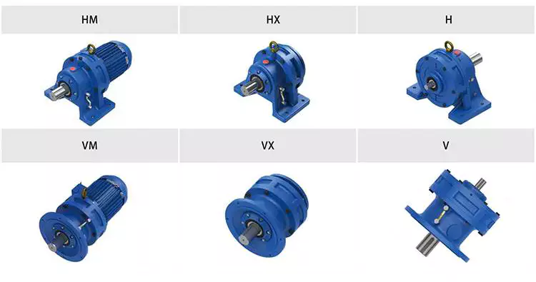
Planetary gearboxes
Compared to cycloidal gearboxes, planetary gearboxes are lighter and more compact, but they lack the precision and durability of the former. They are better suited for applications with high torque or speed requirements. For this reason, they are usually used in robotics applications. But, cycloidal gearboxes are still better for some applications, including those involving shock loads.
There are many factors that affect the performance of gearboxes during production. One of these is the number of teeth. In the case of planetary gearboxes, the number of teeth increases with the number of planets. The number of teeth is reduced in cycloidal gearboxes, which results in higher transmission ratios. These gearboxes also have lower breakaway torques, which means that they can be controlled more easily by the user.
A cycloid gearbox is comprised of three main parts: the ring gear, the sun gear, and the input shaft. The ring gear is fixed in the gearbox, while the sun gear transmits the rotation to the planet gears. The input shaft transfers motion to the sun gear, which in turn transmits it to the output shaft. The output shaft has a larger torque than the input shaft.
Cycloid gears have better torsional stiffness, lower wear, and lower Hertzian contact stress. However, they are also larger in size and require highly accurate manufacturing. Cycloid gears can be more difficult to manufacture than involute gears, which require large amounts of precision.
Cycloid gears can offer transmission ratios up to 300:1, and they can do this in a small package. They also have lower wear and friction, which makes them ideal for applications that require a high transmission ratio.
Cycloid gearboxes are usually equipped with a backlash of about one angular minute. This backlash provides the precision and control necessary for accurate movement. They also provide low wear and shock load capacity.
Planetary gearboxes are available in single and two-stage designs, which increase in length as stages are added. In addition to the two stages, they can be equipped with an optional output bearing, which takes up mounting space. In some applications, a third stage is also available.
Involute gears
Generally, involute gears are more complex to manufacture than cycloidal gears. For example, an involute gear tooth profile has a single curve while a cycloidal gear tooth profile has two curves. In addition, the involute curve is not within the base circle.
The involute curve is a very important component of a gear tooth and it can significantly influence the quality of contact meshing between teeth. Various works have been done on the subject, mainly focusing on the operating principles. In addition, the most important characteristic of the double-enveloping cycloid drive is its double contact lines between the meshing tooth pairs.
Cycloid gears are more powerful, less noisy, and last longer than involute gears. They also require less manufacturing operations during production. However, cycloid gears are more expensive than involute gears. Involute gears are more commonly used in linear motions while cycloid gears are used for rotary motions.
Although cycloid gears are more technically advanced, involute gears have the superior quality and are more aesthetically pleasing. Cycloid gears are used in various industrial applications such as pumps and compressors. They are also widely used in the watch industry. Nevertheless, involute gears have not yet replaced cycloid gears in the watch industry.
The cycloid disc has a number of pins around its outer edge, while an involute gear has only a single curve for the teeth. In addition, cycloid gears have a more robust and reliable design. Involute gears, on the other hand, have a cheaper rack cutter and less expensive involute teeth.
The cycloid disc’s transmission accuracy is about 98.5%, while the ring gear’s transmission accuracy is about 96%. The cycloid disc’s rotational velocity has a magnitude of 3 rad/s. A small change in the center distance does not affect the transmission accuracy. However, rotational velocity fluctuation can affect the transmission accuracy.
Cycloid gears also have the cycloid gear disc’s rotational velocity. The disc has N lobes. However, the cycloid gear disc’s transmission accuracy is still not perfect. This is because of the large rotational angles between the lobes. This also makes it difficult to manufacture.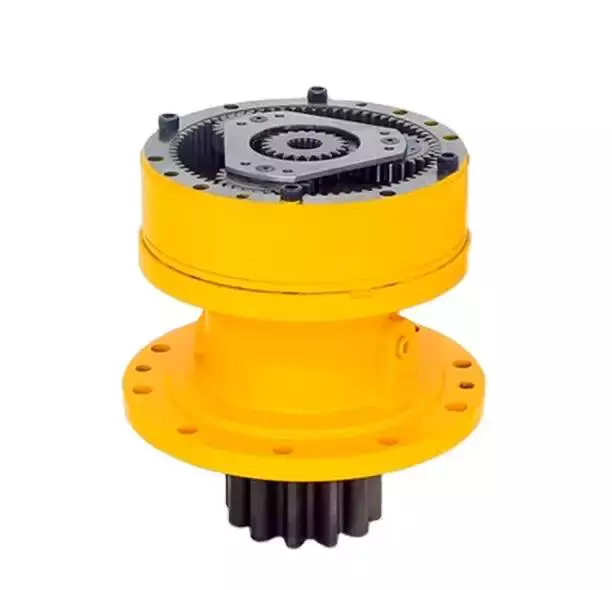
Vibrations
Using modern techniques for vibration diagnostics and data-driven methods, this article presents a new approach to condition monitoring of cycloidal gearboxes. This approach focuses on detecting the root cause of gearbox failure. The article aims to provide a unified approach to gear designers.
A cycloidal gearbox is a high-precision gearbox that is used in heavy-duty machines. It has a large reduction ratio, which makes it necessary to have a very large input speed. Cycloid gears have high accuracy, but they are susceptible to vibration issues. In this article, the authors describe how a cycloidal gearbox works and how vibrations are measured. They also show how this gearbox can be used to detect faults.
The gearbox is used in positioners, multi-axis robots, and heavy-duty machines. The main characteristics of this gearbox are the high accuracy, the overload capacity, and the large reduction ratio.
There is little documentation on vibrations and condition monitoring of cycloidal gearboxes. The authors describe their approach to the problem, using a cycloidal gearbox and a testing bench. Their approach involves measuring the frequency of the gearbox with different input speeds.
The results show a good separation between the healthy and damaged states. Fault frequencies show up in the lower orders of frequencies. Faults can be detected using binning, which eliminates the need for a tachometer. In addition, binning is combined with Principal Component Analysis to determine the state of the gearbox.
This method is compared to traditional techniques. In addition, the results show how binning can be used to calculate the defect frequencies of the bearings. It is also used to determine the frequencies of the components.
The signals from the test bench are acquired using four sensors. These sensors are medium sensitivity 100 mV/g accelerometers. The signals are then processed using different signal processing techniques. The results show that the vibration signals are correlated with the internal motion of the gearbox. This information is used to identify the internal frequency of the transmission.
The frequency analysis of vibration signals is performed in cyclostationary and noncyclostationary conditions. The signals are then analyzed to determine the magnitude of the gear meshing frequency.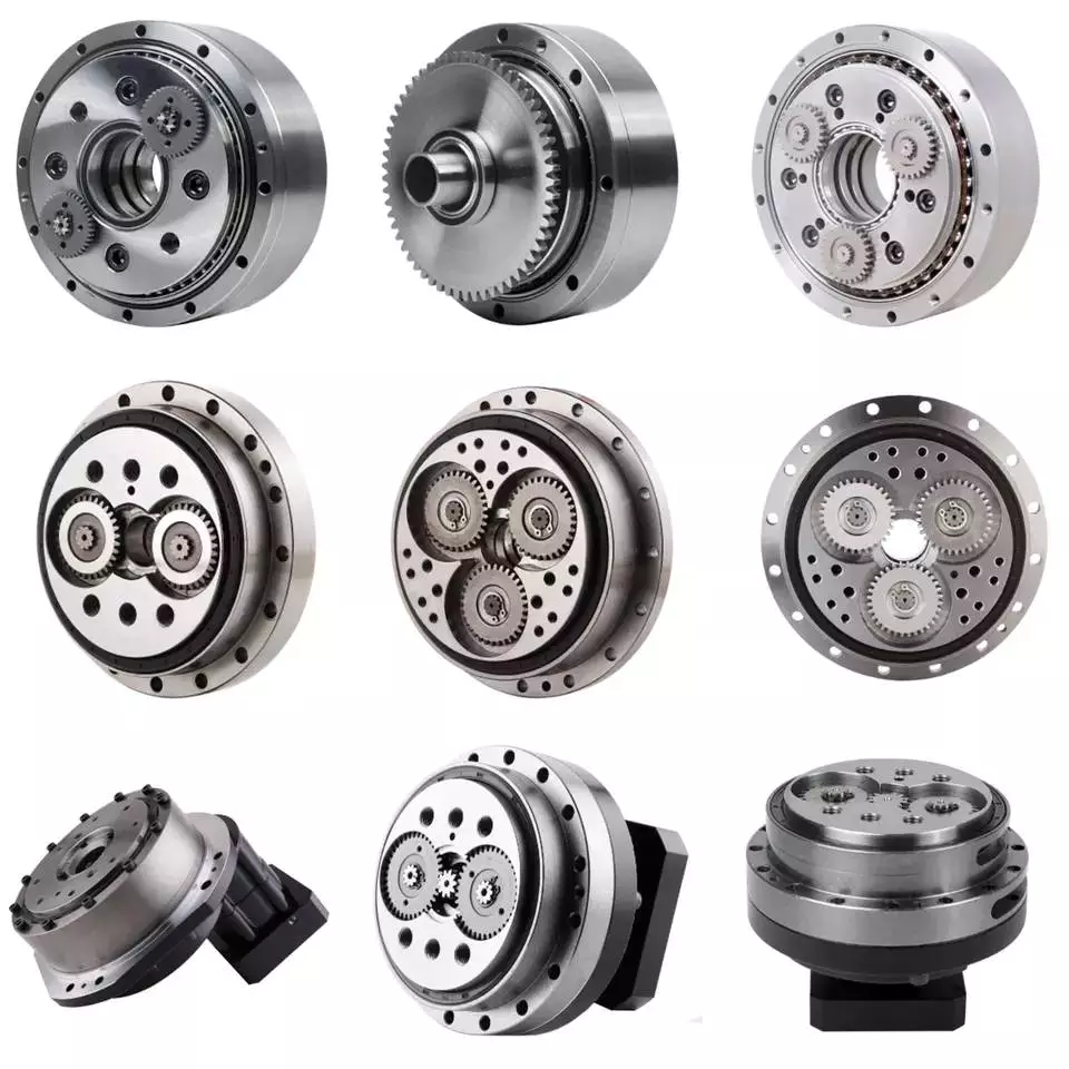
Design
Using precision gearboxes, servomotors can now control heavy loads at high speed. Unlike cam indexing devices, cycloidal gears provide extremely accurate positioning and high torque. They also provide excellent torsional stiffness and shock load capacity.
Cycloid gears are specially designed to minimize vibration at high RPM. Unlike involute gears, they are not stacked, which reduces friction and forces experienced by each tooth. In addition, cycloidal gears have lower Hertzian contact stress.
Cycloid gears are often used in multi-axis robots for positioners. They can provide transmission ratios as high as 300:1 in a compact package. They are also used in first joints in heavy machines. However, they require extremely accurate manufacturing. They are also more difficult to produce than involute gears.
A cycloidal gearbox is a type of planetary gearbox. Cycloid gears are specially designed for high gear ratios. They also have the ability to provide a large reduction ratio in a single stage. They are increasingly used in first joints in heavy machines. They are also becoming more common in robotics.
In order to achieve a large reduction ratio, the input speed of the gear must be very high. Generally, the input speed is between 500 rpm and 4500 rpm. However, in some cases, the input speed may be lower.
A cycloid is formed by rolling a rolling circle on a base circle. The ratio between the rolling circle diameter and the base circle diameter determines the shape of the cycloid. A hypocycloid is formed by rolling primarily on the inside of the base circle, while an epicycloid is formed by rolling primarily on the outside of the base circle.
Cycloid gears have a very small backlash, which minimizes the forces experienced by each tooth. These gears also have a good torsional stiffness, low friction, and shock load capacity. They also provide the best positioning accuracy.
The cycloidal gearbox was designed and built at Radom University. The design was based on three different cycloidal gears. The first pair had the external profile at the nominal dimension, while the second pair had the profile minus tolerance. The load plate had threaded screw holes arranged 15 mm away from the center.

editor by CX 2023-03-30
China Cycloid Gearboxes Servo Bwd Reducer Drive Pinwheel Gear Reducer For Robot Arm Joint gearbox design
Applicable Industries: Vitality & Mining, Other
Excess weight (KG): one hundred KG
Gearing Arrangement: Cycloidal
Output Torque: 2.7~250N.m
Input Pace: 750~3000rpm
Output Speed: 1-100rpm
Solution Title: Cycloid pinwheel reducer
Quality: Exceptional
Mouting kinds: Foot mounted or Vertical mounted
Operate: pace decreasing
Key word: cylcoidal reducer
Function: Lengthy Life
Packaging Specifics: Export regular carton
Port: HangZhou, ZheJiang , ZheJiang
Products Description Lengthy lifestyleVery good and safeStable performanceExcellent qualitySimple to use Details Pictures Product Paramenters Merchandise packaging carton Company Profile China ZheJiang Xihu (West Lake) Dis.chuan Electrical Gear Co., Custom Deep Groove Ball Bearings Substantial High quality Chromium Metal Motor Bearings Ltd., founded in 2015 and positioned in HangZhou, the cash of ZheJiang Province, is a technology business integrating the production and sales of industrial management automation instruments and meters. It is 1 of the suppliers of industrial electrical automation devices and meters in China. We focus on, Needle rolleraxial cylindrical roller bearings blend bearing ZARF3080 rocker arm pivots, pumps, compressors, and transmission professional, committed, integrated manufacturing and sales suppliers, and supply higher-good quality goods and services to buyers at house and abroad for a prolonged time. Income and support community FAQ Query 1: Are you a manufacturing unit? We are a manufacturing facility set up for a lot more than 6 several years and exported for much more than 5 years. Query 2: When is the shipping and delivery day?It typically normally takes 7-10 doing work days.Issue 3: Can you give me an supply? Of program.Concern 4: How about after-product sales support? A few yr warranty.Issue 5: How about transportation packaging? Common cartonQuestion 6: How long will you give me an reply? We will contact you as soon as feasible within 2 hrs.Query 7: Can I get samples for take a look at orders? Sure, High Load self-aligning ball bearing 1200 rs 1200ETN9 open seal bearing we have stock in the warehouse. We can print the merchandise title of your company.
Key Market Insights Related to Worm Reduction Gearboxes
A gearbox is a mechanical device that allows you to shift between different speeds or gears. It does so by using one or more clutches. Some gearboxes are single-clutch, while others use two clutches. You can even find a gearbox with closed bladders. These are also known as dual clutches and can shift gears more quickly than other types. Performance cars are designed with these types of gearboxes.
Backlash measurement
Gearbox backlash is a common component that can cause noise or other problems in a car. In fact, the beats and sets of gears in a gearbox are often excited by the oscillations of the engine torque. Noise from gearboxes can be significant, particularly in secondary shafts that engage output gears with a differential ring. To measure backlash and other dimensional variations, an operator can periodically take the output shaft’s motion and compare it to a known value.
A comparator measures the angular displacement between two gears and displays the results. In one method, a secondary shaft is disengaged from the gearbox and a control gauge is attached to its end. A threaded pin is used to secure the differential crown to the secondary shaft. The output pinion is engaged with the differential ring with the aid of a control gauge. The angular displacement of the secondary shaft is then measured by using the dimensions of the output pinion.
Backlash measurements are important to ensure the smooth rotation of meshed gears. There are various types of backlash, which are classified according to the type of gear used. The first type is called circumferential backlash, which is the length of the pitch circle around which the gear rotates to make contact. The second type, angular backlash, is defined as the maximum angle of movement between two meshed gears, which allows the other gear to move when the other gear is stationary.
The backlash measurement for gearbox is one of the most important tests in the manufacturing process. It is a criterion of tightness or looseness in a gear set, and too much backlash can jam a gear set, causing it to interface on the weaker part of its gear teeth. When backlash is too tight, it can lead to gears jamming under thermal expansion. On the other hand, too much backlash is bad for performance.
Worm reduction gearboxes
Worm reduction gearboxes are used in the production of many different kinds of machines, including steel and power plants. They are also used extensively in the sugar and paper industries. The company is constantly aiming to improve their products and services to remain competitive in the global marketplace. The following is a summary of key market insights related to this type of gearbox. This report will help you make informed business decisions. Read on to learn more about the advantages of this type of gearbox.
Compared to conventional gear sets, worm reduction gearboxes have few disadvantages. Worm gear reducers are commonly available and manufacturers have standardized their mounting dimensions. There are no unique requirements for shaft length, height, and diameter. This makes them a very versatile piece of equipment. You can choose to use one or combine several worm gear reducers to fit your specific application. And because they have standardized ratios, you will not have to worry about matching up multiple gears and determining which ones fit.
One of the primary disadvantages of worm reduction gearboxes is their reduced efficiency. Worm reduction gearboxes usually have a maximum reduction ratio of five to sixty. The higher-performance hypoid gears have an output speed of around ten to twelve revolutions. In these cases, the reduced ratios are lower than those with conventional gearing. Worm reduction gearboxes are generally more efficient than hypoid gear sets, but they still have a low efficiency.
The worm reduction gearboxes have many advantages over traditional gearboxes. They are simple to maintain and can work in a range of different applications. Because of their reduced speed, they are perfect for conveyor belt systems.
Worm reduction gearboxes with closed bladders
The worm and the gear mesh with each other in a combination of sliding and rolling movements. This sliding action is dominant at high reduction ratios, and the worm and gear are made of dissimilar metals, which results in friction and heat. This limits the efficiency of worm gears to around thirty to fifty percent. A softer material for the gear can be used to absorb shock loads during operation.
A normal gear changes its output independently once a sufficient load is applied. However, the backstop complicates the gear configuration. Worm gears require lubrication because of the sliding wear and friction introduced during movement. A common gear arrangement moves power at the peak load section of a tooth. The sliding happens at low speeds on either side of the apex and occurs at a low velocity.
Single-reduction gearboxes with closed bladders may not require a drain plug. The reservoir for a worm gear reducer is designed so that the gears are in constant contact with lubricant. However, the closed bladders will cause the worm gear to wear out more quickly, which can cause premature wear and increased energy consumption. In this case, the gears can be replaced.
Worm gears are commonly used for speed reduction applications. Unlike conventional gear sets, worm gears have higher reduction ratios. The number of gear teeth in the worm reduces the speed of a particular motor by a substantial amount. This makes worm gears an attractive option for hoisting applications. In addition to their increased efficiency, worm gears are compact and less prone to mechanical failure.
Shaft arrangement of a gearbox
The ray-diagram of a gearbox shows the arrangement of gears in the various shafts of the transmission. It also shows how the transmission produces different output speeds from a single speed. The ratios that represent the speed of the spindle are called the step ratio and the progression. A French engineer named Charles Renard introduced five basic series of gearbox speeds. The first series is the gear ratio and the second series is the reverse gear ratio.
The layout of the gear axle system in a gearbox relates to its speed ratio. In general, the speed ratio and the centre distance are coupled by the gear axles to form an efficient transmission. Other factors that may affect the layout of the gear axles include space constraints, the axial dimension, and the stressed equilibrium. In October 2009, the inventors of a manual transmission disclosed the invention as No. 2. These gears can be used to realize accurate gear ratios.
The input shaft 4 in the gear housing 16 is arranged radially with the gearbox output shaft. It drives the lubricating oil pump 2. The pump draws oil from a filter and container 21. It then delivers the lubricating oil into the rotation chamber 3. The chamber extends along the longitudinal direction of the gearbox input shaft 4, and it expands to its maximum diameter. The chamber is relatively large, due to a detent 43.
Different configurations of gearboxes are based on their mounting. The mounting of gearboxes to the driven equipment dictates the arrangement of shafts in the gearbox. In certain cases, space constraints also affect the shaft arrangement. This is the reason why the input shaft in a gearbox may be offset horizontally or vertically. However, the input shaft is hollow, so that it can be connected to lead through lines or clamping sets.
Mounting of a gearbox
In the mathematical model of a gearbox, the mounting is defined as the relationship between the input and output shafts. This is also known as the Rotational Mount. It is one of the most popular types of models used for drivetrain simulation. This model is a simplified form of the rotational mount, which can be used in a reduced drivetrain model with physical parameters. The parameters that define the rotational mount are the TaiOut and TaiIn of the input and output shaft. The Rotational Mount is used to model torques between these two shafts.
The proper mounting of a gearbox is crucial for the performance of the machine. If the gearbox is not aligned properly, it may result in excessive stress and wear. It may also result in malfunctioning of the associated device. Improper mounting also increases the chances of the gearbox overheating or failing to transfer torque. It is essential to ensure that you check the mounting tolerance of a gearbox before installing it in a vehicle.


editor by czh 2023-02-16