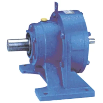
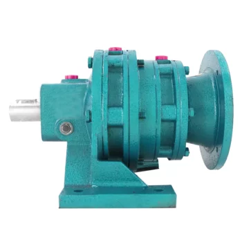
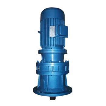
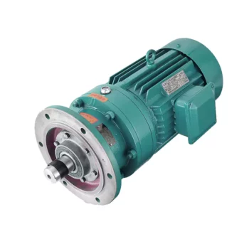
Product Description
Big Torque Cycloidal Gearbox for Impact and Loading Situations
< ABOUT TILI
Technical data
| Product Name | Big Torque Cycloidal Gearbox for Impact and Loading Situations |
| Power | 0.18KW~90KW |
| Torque | 120Nm~30000Nm |
| Running direction | Forward and reverse |
| Gear material | Cast iron |
| Noise test | Below 65dB |
| Brand of bearings | C&U bearing, ZWZ, LYC, HRB, CHINAMFG , etc |
| Brand of oil seal | NAK or other brand |
| Temp. rise (MAX) | 40ºC |
| Temp. rise (Oil)(MAX | 50ºC |
| Vibration | ≤20µm |
| Housing hardness | HBS190-240 |
| Lubricating oil | GB L-CKC220-460, Shell Omala220-460 |
| Heat treatment | Carburizing, Quenching etc |
| Efficiency | 90% (depends on the transmission stage) |
| Installation type | Foot plate horizontal installation, flange type vertical installation; |
| Input method | Flange input(AM), shaft input(AD), inline AC motor input, or AQA servo motor |
Installation Instructions
Company Profile
< WORKSHOP
< QUALITY CONTROL
Certifications
Packaging & Shipping
FAQ
Q 1: Are you a trading company or a manufacturer?
A: We are a professional manufacturer specializing in manufacturing various series of reducer.
Q 2:Can you do OEM?
A:Yes, we can. We can do OEM for all the customers .if you want to order NON-STANDERD speed reducers,pls provide Drafts, Dimensions, Pictures and Samples if possible.
Q 3: How long is your warranty?
A: Our Warranty is 12 months under normal circumstances.
Q 4: Do you have inspection procedures for reducer?
A:100% self-inspection before packing.
Q 5: Can I have a visit to your factory before the order?
A: Sure, welcome to visit our factory.
Q 6:How to choose a gearbox? What if I don’t know which gear reducer I need?
A:You can refer to our catalogue to choose the gearbox or we can help to choose when you provide,the technical information of required output torque, output speed and motor parameter etc. Don’t worry, Send as much information as you can, our team will help you find the right 1 you are looking for.
Q 7: What information shall we give before placing a purchase order?
A:a) Type of the gearbox, Size , Transmission Ratio, input and output type, input flange, mounting position, motor information and shaft deflection etc. b)Housing color.c) Purchase quantity. d) Other special requirements
Q 8:What is the payment term?
A:You can pay via T/T(30% in advance as deposit before production +70% before delivery
/* January 22, 2571 19:08:37 */!function(){function s(e,r){var a,o={};try{e&&e.split(“,”).forEach(function(e,t){e&&(a=e.match(/(.*?):(.*)$/))&&1
| Application: | Motor, Machinery, Agricultural Machinery |
|---|---|
| Function: | Distribution Power, Change Drive Torque, Speed Changing, Speed Reduction |
| Layout: | Cycloidal |
| Customization: |
Available
| Customized Request |
|---|
.shipping-cost-tm .tm-status-off{background: none;padding:0;color: #1470cc}
|
Shipping Cost:
Estimated freight per unit. |
about shipping cost and estimated delivery time. |
|---|
| Payment Method: |
|
|---|---|
|
Initial Payment Full Payment |
| Currency: | US$ |
|---|
| Return&refunds: | You can apply for a refund up to 30 days after receipt of the products. |
|---|

Calculation of Reduction Ratio in a Cycloidal Gearbox
The reduction ratio in a cycloidal gearbox can be calculated using the following formula:
Reduction Ratio = (Number of Input Pins + Number of Output Pins) / Number of Output Pins
In a cycloidal gearbox, the input pins engage with the lobes of the cam disc, while the output pins are engaged with the cycloidal pins of the output rotor. The reduction ratio determines the relationship between the number of input and output pins engaged at any given time.
For example, if a cycloidal gearbox has 7 input pins and 14 output pins engaged, the reduction ratio would be:
Reduction Ratio = (7 + 14) / 14 = 1.5
This means that for every 1 revolution of the input pins, the output rotor will complete 1.5 revolutions. The reduction ratio is a key parameter that influences the output speed and torque of the cycloidal gearbox.

Safety Measures for Operating Cycloidal Gear Systems
Operating cycloidal gear systems requires careful attention to safety to prevent accidents and ensure the well-being of operators and personnel. Here are important safety measures to consider:
- Training: Provide proper training to operators and maintenance personnel on the operation, maintenance, and potential hazards associated with cycloidal gear systems.
- Protective Equipment: Operators should wear appropriate personal protective equipment (PPE) such as gloves, safety glasses, and protective clothing.
- Lockout-Tagout: Implement lockout-tagout procedures to ensure that the system is de-energized and isolated before any maintenance or repair work begins.
- Regular Inspections: Conduct routine inspections of the gear system to identify any signs of wear, damage, or abnormalities that could compromise safety or performance.
- Lubrication: Follow the manufacturer’s recommendations for lubrication to maintain optimal performance and prevent overheating.
- Temperature Monitoring: Install temperature sensors or monitoring devices to detect any excessive heat buildup in the gearbox, which could indicate a potential issue.
- Proper Ventilation: Ensure that the area where the gear system operates is well-ventilated to prevent the accumulation of heat or harmful fumes.
- Emergency Stop: Install emergency stop buttons or switches that can immediately shut down the system in case of an emergency.
- Clearance Zones: Establish clear clearance zones around the gear system to prevent accidental contact with moving parts.
- Regular Maintenance: Follow a scheduled maintenance routine to keep the gear system in optimal working condition and address any potential safety concerns.
- Operator Awareness: Ensure that operators are aware of the gear system’s potential hazards and safe operating practices.
- Warning Signage: Clearly mark areas where the gear system operates with appropriate warning signs and labels.
- Emergency Procedures: Develop and communicate clear emergency procedures to respond to accidents, malfunctions, or other unexpected events.
Prioritizing safety in the operation and maintenance of cycloidal gear systems is essential to prevent injuries and maintain a safe working environment.

Common Applications of Cycloidal Gearboxes
Cycloidal gearboxes find their application in various industries and scenarios where their unique features are advantageous:
- Robotics: Cycloidal gearboxes are often used in robotic joints and manipulators due to their compact size, high torque capacity, and precision movement.
- Conveyor Systems: Their ability to handle heavy loads and provide accurate motion makes cycloidal gearboxes suitable for conveyor systems in industries such as manufacturing, food processing, and material handling.
- Aerospace: In aerospace applications, cycloidal gearboxes are used in satellite mechanisms, aerospace actuators, and precision motion control systems.
- Medical Devices: The compact design and precise motion capabilities of cycloidal gearboxes are beneficial in medical equipment such as surgical robots and diagnostic devices.
- Textile Industry: Cycloidal gearboxes are utilized in textile machines for their ability to provide accurate and synchronized movement in the weaving and knitting processes.
- Automotive: Some automotive applications, such as sunroof mechanisms and power seats, can benefit from the compact size and high torque capacity of cycloidal gearboxes.
- Printing Industry: The precision and reliability of cycloidal gearboxes are important in printing presses to ensure accurate paper feeding and positioning.
- Packaging Machinery: In packaging equipment, cycloidal gearboxes can provide the required torque and accuracy for tasks like sealing, labeling, and filling.
These are just a few examples of where cycloidal gearboxes are commonly used, demonstrating their versatility and adaptability across various industries.


editor by CX 2024-05-14
China factory Large Winding Gearbox with Swing Wheel Assembly Machine sequential gearbox
Product Description
Large Winding Gearbox with Swing Wheel Assembly Machine
This machine is a special automatic machine for the loading of swing
wheel toys in large upward chained gearbox toy. It adopts the latest
technology concept to design a fully automatic unique assembly from plugging,
large upward cHangZhou, oiling, pressing, testing and then discharging, saving
labour and improving work efficiency. The whole set of production line from
loading, dividing, assembling, then optical fiber inspection materials, defective
products reject, and finally to qualified finished products out of the material, to
achieve automatic production, stable and efficient, high compatibility, can
effectively improve market competitiveness.
|
Machine Size |
L2900*W2500*H1900 |
|
Output |
1200-1380pcs/hour |
|
Voltage |
220V 60HZ ≤32A |
|
Power |
8 KW |
|
Control Mode |
PLC Control |
|
Fuselage material |
Aluminium alloy |
|
Special requirement |
Different size is optional |
| Application: | Machinery, Toy |
|---|---|
| Function: | Speed Changing |
| Layout: | Cycloidal |
| Hardness: | Hardened Tooth Surface |
| Installation: | Vertical Type |
| Step: | Four-Step |
| Customization: |
Available
| Customized Request |
|---|

Materials Used in Manufacturing Cycloidal Gearboxes
Cycloidal gearboxes are constructed using a variety of materials to ensure durability, strength, and efficient operation. Some common materials used include:
- Steel: Steel is a popular choice due to its high strength and durability. It can withstand heavy loads and provides excellent wear resistance, making it suitable for industrial applications.
- Aluminum: Aluminum is chosen for its lightweight properties and corrosion resistance. It’s often used in applications where weight is a concern, such as aerospace and robotics.
- Cast Iron: Cast iron offers good heat dissipation and is known for its high resistance to wear and shock. It’s commonly used in heavy-duty applications that require high torque and strength.
- Alloys: Various alloy combinations can be used to enhance specific properties such as corrosion resistance, heat resistance, and strength.
- Plastics and Composites: In some cases, plastic or composite materials may be used, particularly in applications where low noise, lightweight construction, and corrosion resistance are essential.
The material selection depends on factors like the application’s torque, speed, environmental conditions, and desired performance characteristics. Each material offers a unique set of advantages, allowing cycloidal gearboxes to be customized to meet diverse industrial needs.

History of Cycloidal Gear System Development
The history of cycloidal gear systems dates back to ancient times, with various forms of non-circular gears being used for specialized applications. The concept of the cycloidal gear system as we know it today, however, has evolved over centuries of engineering and innovation:
- Ancient Roots: The concept of using non-circular gears can be traced back to ancient civilizations, where devices like the “Antikythera Mechanism” (c. 150-100 BC) employed non-circular gear arrangements.
- Cam Mechanisms: During the Renaissance, engineers and inventors like Leonardo da Vinci explored mechanisms involving cams and followers, which are precursors to modern cycloidal gears.
- Cycloidal Motion Studies: In the 19th century, engineers and mathematicians like Franz Reuleaux and Robert Willis studied and developed mechanisms based on the principles of cycloidal motion.
- Early Cycloidal Gearboxes: The development of cycloidal gear systems gained momentum in the late 19th and early 20th centuries, with inventors like Emile Alluard and Louis André creating early forms of cycloidal gear mechanisms and gearboxes.
- Cycloidal Drive: The term “cycloidal drive” was coined by James Watt in the 18th century, referring to mechanisms that produce a motion resembling a rolling circle.
- Modern Cycloidal Gearboxes: The development of modern cycloidal gearboxes was further advanced by engineers like Ralph B. Heath, who patented the “Harmonic Drive” in the 1950s. This invention marked a significant step in the advancement and commercialization of precision cycloidal gear systems.
- Advancements and Applications: Over the decades, cycloidal gear systems have found applications in robotics, aerospace, automation, and other fields that require compactness, precision, and high torque capabilities.
The history of cycloidal gear system development reflects the contributions of many engineers and inventors who have refined and advanced the technology over time. Today, cycloidal gearboxes continue to play a crucial role in various industries and applications.

What is a Cycloidal Gearbox?
A cycloidal gearbox, also known as a cycloidal drive, is a type of gearing mechanism that utilizes the principle of cycloidal motion for power transmission. It consists of several components, including a high-speed input shaft, a set of cycloidal pins or rollers, and an outer stationary ring with lobed profiles.
The operation of a cycloidal gearbox involves a unique mechanism:
- Input Shaft: The high-speed input shaft is connected to the driving source, such as an electric motor. It transfers rotational motion to the cycloidal pins.
- Cycloidal Pins or Rollers: These pins or rollers are typically arranged around the input shaft in a circular pattern. As the input shaft rotates, the cycloidal pins also rotate, causing them to engage with the lobes on the outer stationary ring.
- Outer Stationary Ring: The outer ring has lobed profiles, and it remains stationary during operation. The lobes of the outer ring interact with the cycloidal pins or rollers, causing them to move in a unique motion known as epicycloidal or hypocycloidal motion.
The interaction between the cycloidal pins and the lobed profiles of the outer ring results in smooth and controlled motion transmission. The mechanism provides advantages such as high torque capacity, compact size, and precise positioning capabilities.
Cycloidal gearboxes are widely used in various applications, including robotics, automation, packaging machinery, and other industrial systems where high torque, precision, and compact design are essential.


editor by CX 2023-10-08