Product Description
Large Winding Gearbox with Swing Wheel Assembly Machine
This machine is a special automatic machine for the loading of swing
wheel toys in large upward chained gearbox toy. It adopts the latest
technology concept to design a fully automatic unique assembly from plugging,
large upward cHangZhou, oiling, pressing, testing and then discharging, saving
labour and improving work efficiency. The whole set of production line from
loading, dividing, assembling, then optical fiber inspection materials, defective
products reject, and finally to qualified finished products out of the material, to
achieve automatic production, stable and efficient, high compatibility, can
effectively improve market competitiveness.
|
Machine Size |
L2900*W2500*H1900 |
|
Output |
1200-1380pcs/hour |
|
Voltage |
220V 60HZ ≤32A |
|
Power |
8 KW |
|
Control Mode |
PLC Control |
|
Fuselage material |
Aluminium alloy |
|
Special requirement |
Different size is optional |
| Application: | Machinery, Toy |
|---|---|
| Function: | Speed Changing |
| Layout: | Cycloidal |
| Hardness: | Hardened Tooth Surface |
| Installation: | Vertical Type |
| Step: | Four-Step |
| Customization: |
Available
| Customized Request |
|---|
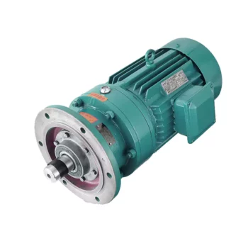
Materials Used in Manufacturing Cycloidal Gearboxes
Cycloidal gearboxes are constructed using a variety of materials to ensure durability, strength, and efficient operation. Some common materials used include:
- Steel: Steel is a popular choice due to its high strength and durability. It can withstand heavy loads and provides excellent wear resistance, making it suitable for industrial applications.
- Aluminum: Aluminum is chosen for its lightweight properties and corrosion resistance. It’s often used in applications where weight is a concern, such as aerospace and robotics.
- Cast Iron: Cast iron offers good heat dissipation and is known for its high resistance to wear and shock. It’s commonly used in heavy-duty applications that require high torque and strength.
- Alloys: Various alloy combinations can be used to enhance specific properties such as corrosion resistance, heat resistance, and strength.
- Plastics and Composites: In some cases, plastic or composite materials may be used, particularly in applications where low noise, lightweight construction, and corrosion resistance are essential.
The material selection depends on factors like the application’s torque, speed, environmental conditions, and desired performance characteristics. Each material offers a unique set of advantages, allowing cycloidal gearboxes to be customized to meet diverse industrial needs.
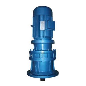
History of Cycloidal Gear System Development
The history of cycloidal gear systems dates back to ancient times, with various forms of non-circular gears being used for specialized applications. The concept of the cycloidal gear system as we know it today, however, has evolved over centuries of engineering and innovation:
- Ancient Roots: The concept of using non-circular gears can be traced back to ancient civilizations, where devices like the “Antikythera Mechanism” (c. 150-100 BC) employed non-circular gear arrangements.
- Cam Mechanisms: During the Renaissance, engineers and inventors like Leonardo da Vinci explored mechanisms involving cams and followers, which are precursors to modern cycloidal gears.
- Cycloidal Motion Studies: In the 19th century, engineers and mathematicians like Franz Reuleaux and Robert Willis studied and developed mechanisms based on the principles of cycloidal motion.
- Early Cycloidal Gearboxes: The development of cycloidal gear systems gained momentum in the late 19th and early 20th centuries, with inventors like Emile Alluard and Louis André creating early forms of cycloidal gear mechanisms and gearboxes.
- Cycloidal Drive: The term “cycloidal drive” was coined by James Watt in the 18th century, referring to mechanisms that produce a motion resembling a rolling circle.
- Modern Cycloidal Gearboxes: The development of modern cycloidal gearboxes was further advanced by engineers like Ralph B. Heath, who patented the “Harmonic Drive” in the 1950s. This invention marked a significant step in the advancement and commercialization of precision cycloidal gear systems.
- Advancements and Applications: Over the decades, cycloidal gear systems have found applications in robotics, aerospace, automation, and other fields that require compactness, precision, and high torque capabilities.
The history of cycloidal gear system development reflects the contributions of many engineers and inventors who have refined and advanced the technology over time. Today, cycloidal gearboxes continue to play a crucial role in various industries and applications.
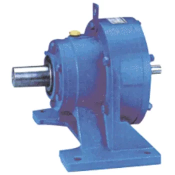
What is a Cycloidal Gearbox?
A cycloidal gearbox, also known as a cycloidal drive, is a type of gearing mechanism that utilizes the principle of cycloidal motion for power transmission. It consists of several components, including a high-speed input shaft, a set of cycloidal pins or rollers, and an outer stationary ring with lobed profiles.
The operation of a cycloidal gearbox involves a unique mechanism:
- Input Shaft: The high-speed input shaft is connected to the driving source, such as an electric motor. It transfers rotational motion to the cycloidal pins.
- Cycloidal Pins or Rollers: These pins or rollers are typically arranged around the input shaft in a circular pattern. As the input shaft rotates, the cycloidal pins also rotate, causing them to engage with the lobes on the outer stationary ring.
- Outer Stationary Ring: The outer ring has lobed profiles, and it remains stationary during operation. The lobes of the outer ring interact with the cycloidal pins or rollers, causing them to move in a unique motion known as epicycloidal or hypocycloidal motion.
The interaction between the cycloidal pins and the lobed profiles of the outer ring results in smooth and controlled motion transmission. The mechanism provides advantages such as high torque capacity, compact size, and precise positioning capabilities.
Cycloidal gearboxes are widely used in various applications, including robotics, automation, packaging machinery, and other industrial systems where high torque, precision, and compact design are essential.


editor by CX 2023-10-08
China Professional Large Winding Gearbox with Swing Wheel Assembly Machine with Hot selling
Product Description
Large Winding Gearbox with Swing Wheel Assembly Machine
This machine is a special automatic machine for the loading of swing
wheel toys in large upward chained gearbox toy. It adopts the latest
technology concept to design a fully automatic unique assembly from plugging,
large upward cHangZhou, oiling, pressing, testing and then discharging, saving
labour and improving work efficiency. The whole set of production line from
loading, dividing, assembling, then optical fiber inspection materials, defective
products reject, and finally to qualified finished products out of the material, to
achieve automatic production, stable and efficient, high compatibility, can
effectively improve market competitiveness.
|
Machine Size |
L2900*W2500*H1900 |
|
Output |
1200-1380pcs/hour |
|
Voltage |
220V 60HZ ≤32A |
|
Power |
8 KW |
|
Control Mode |
PLC Control |
|
Fuselage material |
Aluminium alloy |
|
Special requirement |
Different size is optional |
| Application: | Machinery, Toy |
|---|---|
| Function: | Speed Changing |
| Layout: | Cycloidal |
| Hardness: | Hardened Tooth Surface |
| Installation: | Vertical Type |
| Step: | Four-Step |
| Customization: |
Available
| Customized Request |
|---|

Materials Used in Manufacturing Cycloidal Gearboxes
Cycloidal gearboxes are constructed using a variety of materials to ensure durability, strength, and efficient operation. Some common materials used include:
- Steel: Steel is a popular choice due to its high strength and durability. It can withstand heavy loads and provides excellent wear resistance, making it suitable for industrial applications.
- Aluminum: Aluminum is chosen for its lightweight properties and corrosion resistance. It’s often used in applications where weight is a concern, such as aerospace and robotics.
- Cast Iron: Cast iron offers good heat dissipation and is known for its high resistance to wear and shock. It’s commonly used in heavy-duty applications that require high torque and strength.
- Alloys: Various alloy combinations can be used to enhance specific properties such as corrosion resistance, heat resistance, and strength.
- Plastics and Composites: In some cases, plastic or composite materials may be used, particularly in applications where low noise, lightweight construction, and corrosion resistance are essential.
The material selection depends on factors like the application’s torque, speed, environmental conditions, and desired performance characteristics. Each material offers a unique set of advantages, allowing cycloidal gearboxes to be customized to meet diverse industrial needs.
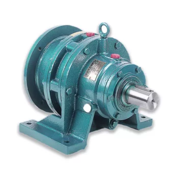
Patents Associated with Cycloidal Gearbox Designs
Throughout the history of cycloidal gearbox development, several patents have been filed for various designs and applications. Some notable patents include:
- Harmonic Drive: Ralph B. Heath’s patent for the “Harmonic Drive” (US Patent 2,906,143), filed in 1957, is one of the most famous patents related to cycloidal gear systems. This patent introduced the concept of a high-precision reduction gear mechanism using flexible components.
- Cycloidal Drive Mechanism: A patent by James Watt for a “Cycloidal Drive Mechanism” (GB Patent 1812), dating back to the 18th century, is often cited as one of the early references to cycloidal motion and gears.
- Planetary Roller Transmission: US Patent 3,671,927 by C.F. Kafesjian and H. Blumenstock introduced a “Planetary Roller Transmission” in 1972, describing a cycloidal drive mechanism with planetary motion.
- Cycloidal Speed Reducer: A patent for a “Cycloidal Speed Reducer” (US Patent 5,588,583) was granted to Richard J. Pieprzak in 1996, focusing on an improved design of cycloidal gears for various applications.
These patents represent a small sample of the numerous innovations and designs related to cycloidal gear systems that have been patented over the years. Patents play a significant role in protecting and promoting innovation in the field of gearbox technology.

What is a Cycloidal Gearbox?
A cycloidal gearbox, also known as a cycloidal drive, is a type of gearing mechanism that utilizes the principle of cycloidal motion for power transmission. It consists of several components, including a high-speed input shaft, a set of cycloidal pins or rollers, and an outer stationary ring with lobed profiles.
The operation of a cycloidal gearbox involves a unique mechanism:
- Input Shaft: The high-speed input shaft is connected to the driving source, such as an electric motor. It transfers rotational motion to the cycloidal pins.
- Cycloidal Pins or Rollers: These pins or rollers are typically arranged around the input shaft in a circular pattern. As the input shaft rotates, the cycloidal pins also rotate, causing them to engage with the lobes on the outer stationary ring.
- Outer Stationary Ring: The outer ring has lobed profiles, and it remains stationary during operation. The lobes of the outer ring interact with the cycloidal pins or rollers, causing them to move in a unique motion known as epicycloidal or hypocycloidal motion.
The interaction between the cycloidal pins and the lobed profiles of the outer ring results in smooth and controlled motion transmission. The mechanism provides advantages such as high torque capacity, compact size, and precise positioning capabilities.
Cycloidal gearboxes are widely used in various applications, including robotics, automation, packaging machinery, and other industrial systems where high torque, precision, and compact design are essential.


editor by CX 2023-10-07
China best Large Winding Gearbox with Swing Wheel Assembly Machine car gearbox
Product Description
Large Winding Gearbox with Swing Wheel Assembly Machine
This machine is a special automatic machine for the loading of swing
wheel toys in large upward chained gearbox toy. It adopts the latest
technology concept to design a fully automatic unique assembly from plugging,
large upward cHangZhou, oiling, pressing, testing and then discharging, saving
labour and improving work efficiency. The whole set of production line from
loading, dividing, assembling, then optical fiber inspection materials, defective
products reject, and finally to qualified finished products out of the material, to
achieve automatic production, stable and efficient, high compatibility, can
effectively improve market competitiveness.
|
Machine Size |
L2900*W2500*H1900 |
|
Output |
1200-1380pcs/hour |
|
Voltage |
220V 60HZ ≤32A |
|
Power |
8 KW |
|
Control Mode |
PLC Control |
|
Fuselage material |
Aluminium alloy |
|
Special requirement |
Different size is optional |
| Application: | Machinery, Toy |
|---|---|
| Function: | Speed Changing |
| Layout: | Cycloidal |
| Hardness: | Hardened Tooth Surface |
| Installation: | Vertical Type |
| Step: | Four-Step |
| Customization: |
Available
| Customized Request |
|---|
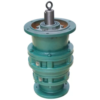
Distinguishing Features of Cycloidal Gearboxes
Cycloidal gearboxes, also known as cycloidal drives or cycloidal reducers, possess distinct characteristics that set them apart from other types of gearboxes:
- Principle of Operation: Cycloidal gearboxes utilize the principle of cycloidal motion, where input shaft movement is transformed into eccentric motion of the cycloidal disc. This unique mechanism results in smooth and consistent output motion.
- Compactness: Cycloidal gearboxes are renowned for their compact size and high torque density. The concentric design of the components contributes to their ability to transmit substantial torque in a relatively small package.
- Tooth Profile: Cycloidal gearboxes employ specialized cycloidal teeth, which involve both pinwheel and roller gears. This distinctive tooth profile contributes to the characteristic smooth and vibration-free operation.
- Reduction Mechanism: They often employ multi-lobed cam gears that interact with the pins on the cycloidal disc, resulting in multiple gear engagements per revolution and improved load distribution.
- Motion Control: Cycloidal gearboxes offer high positional accuracy and motion control due to the eccentric motion of the disc, making them suitable for robotics, automation, and precision applications.
- Backlash: They typically exhibit low backlash due to the nature of the engagement mechanism, making them advantageous for applications requiring precise and reversible motion.
- Applications: Cycloidal gearboxes are commonly used in various industries, including robotics, packaging, material handling, printing, and more, where their compactness, precision, and efficiency are valued.
These distinguishing features contribute to the unique capabilities and benefits of cycloidal gearboxes in specific applications.
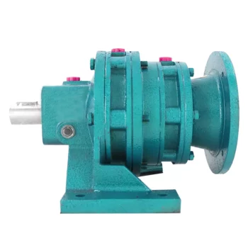
Safety Measures for Operating Cycloidal Gear Systems
Operating cycloidal gear systems requires careful attention to safety to prevent accidents and ensure the well-being of operators and personnel. Here are important safety measures to consider:
- Training: Provide proper training to operators and maintenance personnel on the operation, maintenance, and potential hazards associated with cycloidal gear systems.
- Protective Equipment: Operators should wear appropriate personal protective equipment (PPE) such as gloves, safety glasses, and protective clothing.
- Lockout-Tagout: Implement lockout-tagout procedures to ensure that the system is de-energized and isolated before any maintenance or repair work begins.
- Regular Inspections: Conduct routine inspections of the gear system to identify any signs of wear, damage, or abnormalities that could compromise safety or performance.
- Lubrication: Follow the manufacturer’s recommendations for lubrication to maintain optimal performance and prevent overheating.
- Temperature Monitoring: Install temperature sensors or monitoring devices to detect any excessive heat buildup in the gearbox, which could indicate a potential issue.
- Proper Ventilation: Ensure that the area where the gear system operates is well-ventilated to prevent the accumulation of heat or harmful fumes.
- Emergency Stop: Install emergency stop buttons or switches that can immediately shut down the system in case of an emergency.
- Clearance Zones: Establish clear clearance zones around the gear system to prevent accidental contact with moving parts.
- Regular Maintenance: Follow a scheduled maintenance routine to keep the gear system in optimal working condition and address any potential safety concerns.
- Operator Awareness: Ensure that operators are aware of the gear system’s potential hazards and safe operating practices.
- Warning Signage: Clearly mark areas where the gear system operates with appropriate warning signs and labels.
- Emergency Procedures: Develop and communicate clear emergency procedures to respond to accidents, malfunctions, or other unexpected events.
Prioritizing safety in the operation and maintenance of cycloidal gear systems is essential to prevent injuries and maintain a safe working environment.

Principle of Cycloidal Gearing
Cycloidal gearing is a mechanism that utilizes the unique shape of cycloidal discs to achieve motion transmission. The principle involves the interaction between two main components: the input disc and the output disc.
The input disc has lobes with pins, while the output disc has lobes with matching holes. The lobes on both discs are not perfectly circular but are shaped in a cycloidal profile. As the input disc rotates, the pins on its lobes engage with the holes in the output disc’s lobes.
As the input disc rotates, the pins move along the cycloidal paths, causing the output disc to rotate. The interaction between the pins and the holes results in smooth and continuous motion transfer. The unique shape of the cycloidal profile ensures that there is always at least one point of contact between the pins and the holes, allowing for efficient torque transmission and reduced wear.
Cycloidal gearing provides advantages such as high torque capacity, compact size, and precision motion. However, due to the complex shape of the components and the continuous engagement, manufacturing and assembly of cycloidal gearboxes can be intricate.


editor by CX 2023-09-28
China 30r/m 0.6KW 150BX REA Series High Precision Cycloidal Gearbox with Flange for Robot Arm cycloidal gearbox assembly
Merchandise Description
30r/m .6KW 150BX REA Collection Higher Precision Cycloidal Gearbox with Flange for Robot Arm
Product:150BX-REA-19
More Code And Specification:
| E sequence | C series | ||||
| Code | Define dimension | General product | Code | Outline dimension | The authentic code |
| a hundred and twenty | Φ122 | 6E | 10C | Φ145 | a hundred and fifty |
| 150 | Φ145 | 20E | 27C | Φ181 | one hundred eighty |
| one hundred ninety | Φ190 | 40E | 50C | Φ222 | 220 |
| 220 | Φ222 | 80E | 100C | Φ250 | 250 |
| 250 | Φ244 | 110E | 200C | Φ345 | 350 |
| 280 | Φ280 | 160E | 320C | Φ440 | 440 |
| 320 | Φ325 | 320E | 500C | Φ520 | 520 |
| 370 | Φ370 | 450E | |||
Gear ratio And Specification
| E Collection | C Collection | ||
| Code | Reduction Ratio | New code | Monomer reduction ratio |
| one hundred twenty | forty three,53.5,59,79,103 | 10CBX | 27.00 |
| a hundred and fifty | eighty one,one zero five,121,141,161 | 27CBX | 36.fifty seven |
| 190 | 81,one zero five,121,153 | 50CBX | 32.54 |
| 220 | eighty one,one hundred and one,121,153 | 100CBX | 36.75 |
| 250 | 81,111,161,a hundred seventy five.28 | 200CBX | 34.86 |
| 280 | eighty one,101,129,145,171 | 320CBX | 35.61 |
| 320 | 81,a hundred and one,118.5,129,141,171,185 | 500CBX | 37.34 |
| 370 | 81,one zero one,118.5,129,154.8,171,192.4 | ||
| Note 1: E collection,this kind of as by the shell(pin shell)output,the corresponding reduction ratio by 1 | |||
| Note 2: C collection gear ratio refers to the motor put in in the casing of the reduction ratio,if installed on the output flange side,the corresponding reduction ratio by 1 | |||
Reducer variety code
REV: main bearing built-in E sort
RVC: hollow kind
REA: with enter flange E variety
RCA: with input flange hollow type
Software:
Business Information
FAQ
Q: What’re your major merchandise?
A: We presently generate Brushed Dc Motors, Brushed Dc Gear Motors, Planetary Dc Gear Motors, Brushless Dc Motors, Stepper motors, Ac Motors and Higher Precision Planetary Gear Box and so on. You can check out the specs for earlier mentioned motors on our site and you can email us to recommend required motors for every your specification also.
Q: How to decide on a suitable motor?
A:If you have motor photos or drawings to show us, or you have detailed specs like voltage, pace, torque, motor dimensions, operating manner of the motor, essential lifetime and noise level and so forth, make sure you do not wait to enable us know, then we can advise appropriate motor for every your ask for accordingly.
Q: Do you have a personalized provider for your regular motors?
A: Yes, we can personalize per your ask for for the voltage, pace, torque and shaft dimensions/form. If you require further wires/cables soldered on the terminal or need to have to insert connectors, or capacitors or EMC we can make it way too.
Q: Do you have an specific design provider for motors?
A: Yes, we would like to design and style motors independently for our buyers, but it may possibly need some mould creating price and style cost.
Q: What’s your lead time?
A: Generally speaking, our typical normal merchandise will require 15-30days, a little bit lengthier for personalized goods. But we are quite flexible on the guide time, it will rely on the particular orders.
Please speak to us if you have comprehensive requests, thank you !
| To Be Negotiated | 1 Piece (Min. Order) |
###
| Application: | Machinery, Robotic |
|---|---|
| Hardness: | Hardened Tooth Surface |
| Installation: | Vertical Type |
| Layout: | Coaxial |
| Gear Shape: | Cylindrical Gear |
| Step: | Double-Step |
###
| Customization: |
|---|
###
| E series | C series | ||||
| Code | Outline dimension | General model | Code | Outline dimension | The original code |
| 120 | Φ122 | 6E | 10C | Φ145 | 150 |
| 150 | Φ145 | 20E | 27C | Φ181 | 180 |
| 190 | Φ190 | 40E | 50C | Φ222 | 220 |
| 220 | Φ222 | 80E | 100C | Φ250 | 250 |
| 250 | Φ244 | 110E | 200C | Φ345 | 350 |
| 280 | Φ280 | 160E | 320C | Φ440 | 440 |
| 320 | Φ325 | 320E | 500C | Φ520 | 520 |
| 370 | Φ370 | 450E | |||
###
| E Series | C Series | ||
| Code | Reduction Ratio | New code | Monomer reduction ratio |
| 120 | 43,53.5,59,79,103 | 10CBX | 27.00 |
| 150 | 81,105,121,141,161 | 27CBX | 36.57 |
| 190 | 81,105,121,153 | 50CBX | 32.54 |
| 220 | 81,101,121,153 | 100CBX | 36.75 |
| 250 | 81,111,161,175.28 | 200CBX | 34.86 |
| 280 | 81,101,129,145,171 | 320CBX | 35.61 |
| 320 | 81,101,118.5,129,141,171,185 | 500CBX | 37.34 |
| 370 | 81,101,118.5,129,154.8,171,192.4 | ||
| Note 1: E series,such as by the shell(pin shell)output,the corresponding reduction ratio by 1 | |||
| Note 2: C series gear ratio refers to the motor installed in the casing of the reduction ratio,if installed on the output flange side,the corresponding reduction ratio by 1 | |||
Condition Monitoring of Cyclone Gearboxes
Whether you’re considering using a cycloidal gearbox in your home, office, or garage, you’ll want to make sure it’s made of quality material. You also want to make sure it’s designed properly, so it won’t be damaged by vibrations.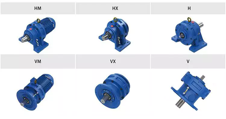
Planetary gearboxes
Compared to cycloidal gearboxes, planetary gearboxes are lighter and more compact, but they lack the precision and durability of the former. They are better suited for applications with high torque or speed requirements. For this reason, they are usually used in robotics applications. But, cycloidal gearboxes are still better for some applications, including those involving shock loads.
There are many factors that affect the performance of gearboxes during production. One of these is the number of teeth. In the case of planetary gearboxes, the number of teeth increases with the number of planets. The number of teeth is reduced in cycloidal gearboxes, which results in higher transmission ratios. These gearboxes also have lower breakaway torques, which means that they can be controlled more easily by the user.
A cycloid gearbox is comprised of three main parts: the ring gear, the sun gear, and the input shaft. The ring gear is fixed in the gearbox, while the sun gear transmits the rotation to the planet gears. The input shaft transfers motion to the sun gear, which in turn transmits it to the output shaft. The output shaft has a larger torque than the input shaft.
Cycloid gears have better torsional stiffness, lower wear, and lower Hertzian contact stress. However, they are also larger in size and require highly accurate manufacturing. Cycloid gears can be more difficult to manufacture than involute gears, which require large amounts of precision.
Cycloid gears can offer transmission ratios up to 300:1, and they can do this in a small package. They also have lower wear and friction, which makes them ideal for applications that require a high transmission ratio.
Cycloid gearboxes are usually equipped with a backlash of about one angular minute. This backlash provides the precision and control necessary for accurate movement. They also provide low wear and shock load capacity.
Planetary gearboxes are available in single and two-stage designs, which increase in length as stages are added. In addition to the two stages, they can be equipped with an optional output bearing, which takes up mounting space. In some applications, a third stage is also available.
Involute gears
Generally, involute gears are more complex to manufacture than cycloidal gears. For example, an involute gear tooth profile has a single curve while a cycloidal gear tooth profile has two curves. In addition, the involute curve is not within the base circle.
The involute curve is a very important component of a gear tooth and it can significantly influence the quality of contact meshing between teeth. Various works have been done on the subject, mainly focusing on the operating principles. In addition, the most important characteristic of the double-enveloping cycloid drive is its double contact lines between the meshing tooth pairs.
Cycloid gears are more powerful, less noisy, and last longer than involute gears. They also require less manufacturing operations during production. However, cycloid gears are more expensive than involute gears. Involute gears are more commonly used in linear motions while cycloid gears are used for rotary motions.
Although cycloid gears are more technically advanced, involute gears have the superior quality and are more aesthetically pleasing. Cycloid gears are used in various industrial applications such as pumps and compressors. They are also widely used in the watch industry. Nevertheless, involute gears have not yet replaced cycloid gears in the watch industry.
The cycloid disc has a number of pins around its outer edge, while an involute gear has only a single curve for the teeth. In addition, cycloid gears have a more robust and reliable design. Involute gears, on the other hand, have a cheaper rack cutter and less expensive involute teeth.
The cycloid disc’s transmission accuracy is about 98.5%, while the ring gear’s transmission accuracy is about 96%. The cycloid disc’s rotational velocity has a magnitude of 3 rad/s. A small change in the center distance does not affect the transmission accuracy. However, rotational velocity fluctuation can affect the transmission accuracy.
Cycloid gears also have the cycloid gear disc’s rotational velocity. The disc has N lobes. However, the cycloid gear disc’s transmission accuracy is still not perfect. This is because of the large rotational angles between the lobes. This also makes it difficult to manufacture.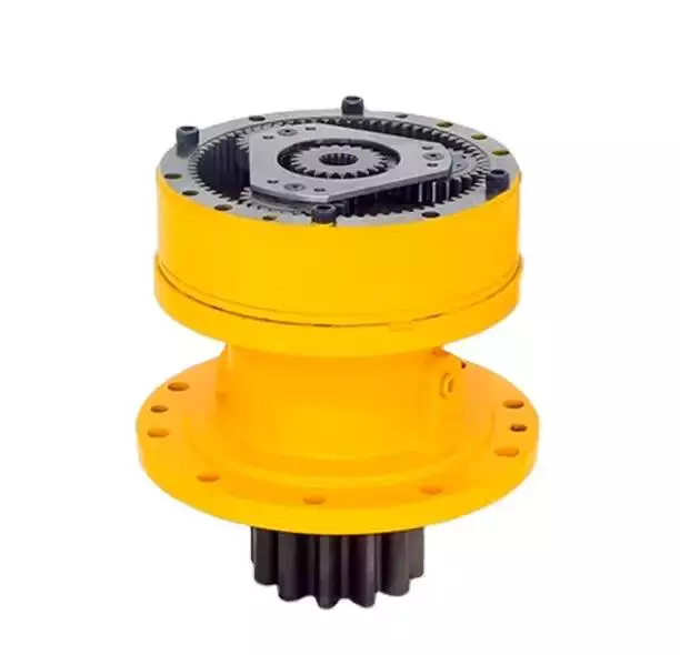
Vibrations
Using modern techniques for vibration diagnostics and data-driven methods, this article presents a new approach to condition monitoring of cycloidal gearboxes. This approach focuses on detecting the root cause of gearbox failure. The article aims to provide a unified approach to gear designers.
A cycloidal gearbox is a high-precision gearbox that is used in heavy-duty machines. It has a large reduction ratio, which makes it necessary to have a very large input speed. Cycloid gears have high accuracy, but they are susceptible to vibration issues. In this article, the authors describe how a cycloidal gearbox works and how vibrations are measured. They also show how this gearbox can be used to detect faults.
The gearbox is used in positioners, multi-axis robots, and heavy-duty machines. The main characteristics of this gearbox are the high accuracy, the overload capacity, and the large reduction ratio.
There is little documentation on vibrations and condition monitoring of cycloidal gearboxes. The authors describe their approach to the problem, using a cycloidal gearbox and a testing bench. Their approach involves measuring the frequency of the gearbox with different input speeds.
The results show a good separation between the healthy and damaged states. Fault frequencies show up in the lower orders of frequencies. Faults can be detected using binning, which eliminates the need for a tachometer. In addition, binning is combined with Principal Component Analysis to determine the state of the gearbox.
This method is compared to traditional techniques. In addition, the results show how binning can be used to calculate the defect frequencies of the bearings. It is also used to determine the frequencies of the components.
The signals from the test bench are acquired using four sensors. These sensors are medium sensitivity 100 mV/g accelerometers. The signals are then processed using different signal processing techniques. The results show that the vibration signals are correlated with the internal motion of the gearbox. This information is used to identify the internal frequency of the transmission.
The frequency analysis of vibration signals is performed in cyclostationary and noncyclostationary conditions. The signals are then analyzed to determine the magnitude of the gear meshing frequency.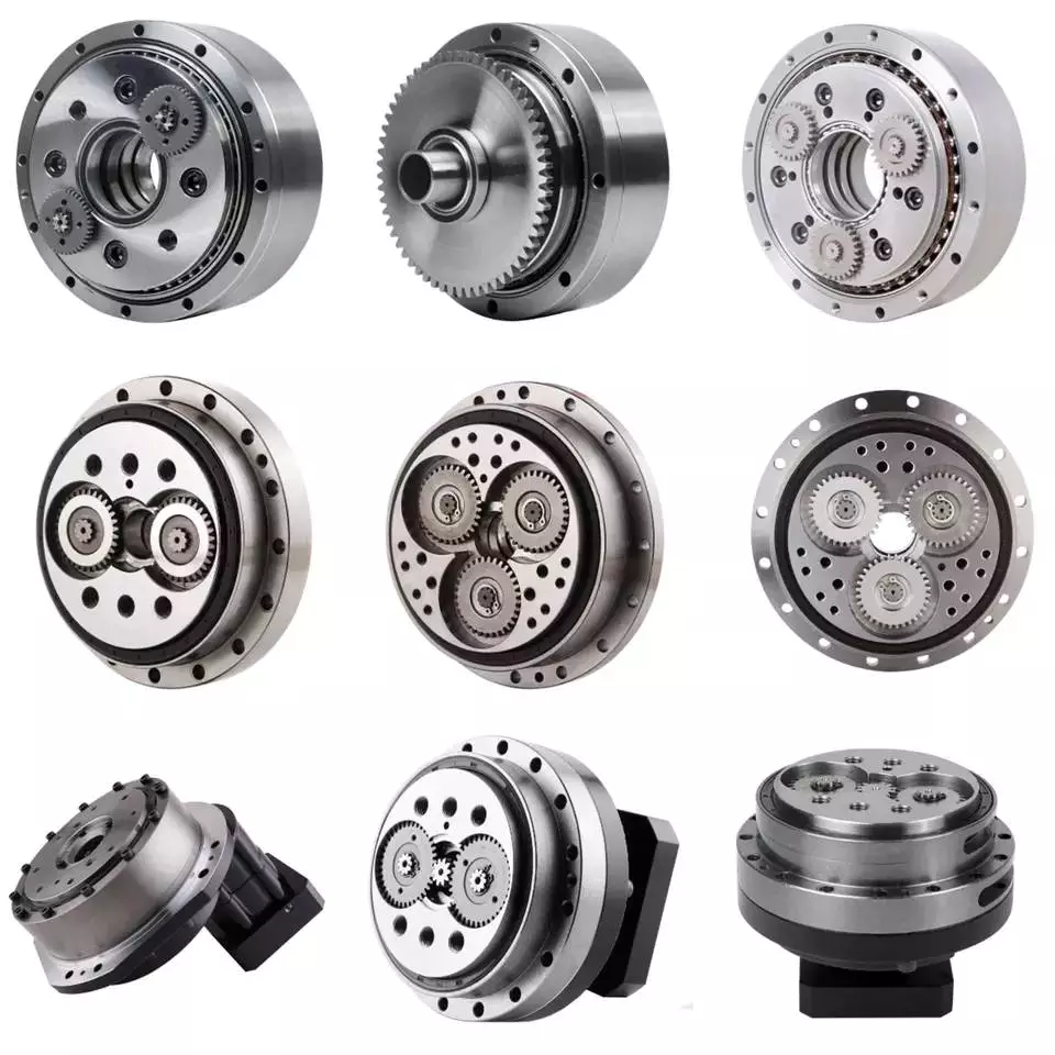
Design
Using precision gearboxes, servomotors can now control heavy loads at high speed. Unlike cam indexing devices, cycloidal gears provide extremely accurate positioning and high torque. They also provide excellent torsional stiffness and shock load capacity.
Cycloid gears are specially designed to minimize vibration at high RPM. Unlike involute gears, they are not stacked, which reduces friction and forces experienced by each tooth. In addition, cycloidal gears have lower Hertzian contact stress.
Cycloid gears are often used in multi-axis robots for positioners. They can provide transmission ratios as high as 300:1 in a compact package. They are also used in first joints in heavy machines. However, they require extremely accurate manufacturing. They are also more difficult to produce than involute gears.
A cycloidal gearbox is a type of planetary gearbox. Cycloid gears are specially designed for high gear ratios. They also have the ability to provide a large reduction ratio in a single stage. They are increasingly used in first joints in heavy machines. They are also becoming more common in robotics.
In order to achieve a large reduction ratio, the input speed of the gear must be very high. Generally, the input speed is between 500 rpm and 4500 rpm. However, in some cases, the input speed may be lower.
A cycloid is formed by rolling a rolling circle on a base circle. The ratio between the rolling circle diameter and the base circle diameter determines the shape of the cycloid. A hypocycloid is formed by rolling primarily on the inside of the base circle, while an epicycloid is formed by rolling primarily on the outside of the base circle.
Cycloid gears have a very small backlash, which minimizes the forces experienced by each tooth. These gears also have a good torsional stiffness, low friction, and shock load capacity. They also provide the best positioning accuracy.
The cycloidal gearbox was designed and built at Radom University. The design was based on three different cycloidal gears. The first pair had the external profile at the nominal dimension, while the second pair had the profile minus tolerance. The load plate had threaded screw holes arranged 15 mm away from the center.

editor by CX 2023-04-07
China Factory supple Daihatsu Delta truck, Van, Crown, Hiace, Hilux, forklift 4Y gearbox transmission assembly for sale gearbox and motor
Applicable Industries: Equipment Restore Stores, Retail, Other
Excess weight (KG): 35
Tailored help: OEM
Gearing Arrangement: Cycloidal
Output Torque: eight
Packaging Details: wood box for Factory supple Daihatsu Delta truck, Van, Nema 23 Stepper motor 1.2Nm set motor 4pcs LLU ZZ 2RS 6309 zz deep groove ball bearing DHL, TNT,UPS
Types of Gearboxes
There are several types of gearboxes. Some are known as helical gear reducers, while others are called planetary gearboxes. The article also discusses Continuously Variable Transmission (CVT) and helical gear reducer. If you are interested in purchasing a new gearbox, make sure to read our articles on these different types. If you are confused, consider reading our articles on planetary gearboxes and helical gear reducers.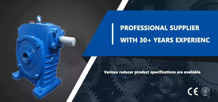
planetary gearbox
The planetary gearbox has several advantages. Its compact design and light weight allows it to transmit high torques while remaining quiet. The gears are connected to one another through a carrier, which is typically fixed and helps transmit torques to the output shaft. Its planetary structure arrangement also reduces backlash and provides high rigidity, which is important for quick start and stop cycles and rotational direction change. Depending on the design and performance desired, planetary gearboxes are categorized into three main types:
The type of planetary gears used in a given application determines the overall cost of the unit. Manufacturers offer a range of prices, and they can help you determine which gearbox is right for your needs. You should also ask a manufacturer for the cost of a planetary gearbox. By asking about price and specs, you can avoid wasting money and time on a planetary gearbox that does not perform up to its potential.
A planetary gearbox is probably installed in your new car’s automatic transmission. For more information, consult your owner’s manual or call the dealer’s service department. This type of gearbox is more complex than other types of gearboxes, so if you don’t know much about them, do an internet search for “planetary gearbox.”
The teeth of a planetary gearbox are formed by the stepping motion of two gears: the sun gear and the inner ring. The sun gear is the input, while the planetary gears rotate around the sun gear. Their ratio depends on the number of teeth and the space between the planets. If you have a 24 tooth sun gear, the planetary gears’ ratio will be -3/2. The sun gear is also attached to the axle.
Another advantage of a planetary gear system is that it can generate high torques. The load is shared among multiple planet gears. This makes the gears more resilient to damage. A planetary gearbox can be as high as 332,000 Nm, and can be used in vehicles and industrial applications requiring medium to high torque. A planetary gear system is a great alternative to a traditional transmission. So, how does it work?
helical gearbox
The main difference between the helical gearbox and the spur gear is the center distance between the teeth. The helical gearbox has a larger pitch circle than the spur gear and thus requires a radial module. In addition, the two types of gears can only be made with the same tooth-cutting tool as the spur gear. However, the helical gearbox is more efficient in terms of production costs.
The helical gearbox is a low-power consumption, compact type of gearbox that is used for a wide range of industrial applications. They are highly durable and withstand high loads with utmost efficiency. The helical gearbox can be manufactured in cast steel and iron for small and medium units. This type of gearbox is also commonly used for crushers, conveyors, coolers, and other applications that need low power.
The helical gear has many advantages over the spur gear. It produces less noise. It has less friction and is less likely to wear out. It is also quieter than spur gears. This is because multiple teeth are in mesh. Because the teeth are in mesh, the load is distributed over a larger area, resulting in a smoother transition between gears. The reduction in noise and vibration reduces the risk of damaging the gear.
The helical gear’s axial excitation force is obtained using a linearized equation of motion in the rotational direction. The damping coefficient of the equation is 0.07. The helical gear is made up of a steel shaft with a diameter of 20 mm and a 5 mm thick aluminum plate. The stiffness of the bearing is 6.84 x 10⁷ N/m. The damping force of the plate is 2,040 kg/m2/s.
The worm gearbox has a better efficiency ratio than the helical one, but it is less efficient in low-ratio applications. In general, worm gearboxes are more efficient than helical gearboxes, although there are some exceptions to this rule. A helical gearbox is better for applications that require high torque. It may also be more economical in the long run. If you are considering a helical gearbox, consider the advantages it has over worm gearboxes.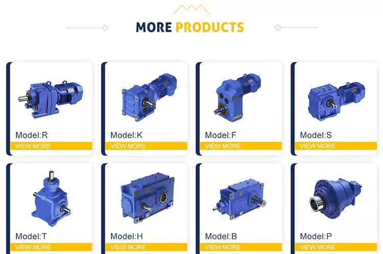
helical gear reducer
A helical gear reducer for a machine’s gearbox is an integral component of the drive system. This unit amplifies torque and controls speed and, therefore, compliments the engine by rotating slower than the engine’s input shaft. A helical gear reducer is a compact gearbox component that is used in industrial applications. A variety of sizes is available to suit various machine configurations. The following sections will discuss some of the different types available.
Designed by experts and engineers, a helical gear reducer is a surprisingly small and light gear that satisfies the needs of many machine applications. It features a large transmission torque, a low starting and running speed, and a fine classification of transmission ratios. A helical gear reducer is lightweight and easily connected to other gears, and it features a high technical content.
In order to avoid errors and poor performance, regular maintenance is a must. The proper lubrication of the gear reducer can minimize failures, errors, and poor performance. Every gear reducer manufacturer sells a suitable lubricant, which must match the properties of the machine’s drive mechanism. It is also advisable to check the lubrication regularly to avoid any deterioration of the unit’s performance.
While the worm gearbox may be better for applications where torque is high, the helical gear reducer offers greater efficiency at lower cost. Although worm gearboxes may be cheaper initially, they are less effective at higher ratios. Even if the worm gear is more expensive to buy, it still offers 94% efficiency, which makes it more cost-effective. There are some significant advantages to both types of gearboxes.
The main advantage of a helical gear reducer over a spur gear is its smoother operation. Unlike spur gears, which have teeth that are straight, helical gears have angled teeth that gradually engage with each other. This helps ensure that the gear does not grind or make excessive noise when it turns. Additionally, they are less commonly used in automation and precision machinery. They are often used in industrial applications.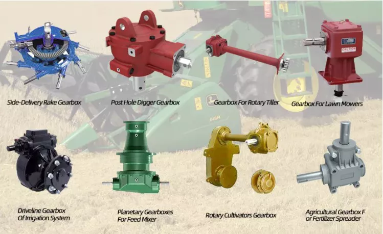
Continuously variable transmission
A Continuously Variable Transmission (CVT) is an automatic transmission that can run through a vast number of gears. Unlike a standard automatic transmission, it can run at any speed, even at a low rev. The CVT is also capable of running at infinitely low gears. Its basic function is to provide different torque ratios to the engine. In addition to delivering power, CVTs have other benefits.
One of the major advantages of a CVT is its simplicity. Its simplicity translates into fewer moving parts, which means less maintenance. The CVT’s simplicity also means that it can handle a wide variety of different types of road conditions and driving styles. In addition to being a great alternative to a traditional automatic transmission, CVTs can be used on many other types of vehicles, including tractors, snowmobiles, motor scooters, and power tools.
A CVT is much smoother than a conventional automatic transmission. It never has to hunt for a gear. It also responds well to throttle inputs and speed changes. Both of these technologies are available on many modern vehicles, including the Nissan Rogue and Mazda CX-5. It’s important to note that each of these transmissions has its pros and cons. So, if you’re looking for a car with a CVT, make sure to read the reviews. They’ll help you decide which transmission is right for you.
Another advantage of a CVT is its fuel efficiency. Many cars now feature CVTs, and they’re becoming increasingly popular with automakers. In addition to fuel efficiency, most cars with CVTs also have a smoother ride. There’s no more sudden downshifts or gear hunting. This makes driving a lot easier. And, the added benefits of smoother driving make CVTs the ideal choice for many drivers.
Although a CVT is more common among Japanese car manufacturers, you’ll find CVTs on European car models as well. The Mercedes-Benz A-Class, B-Class, and Megane are some examples of vehicles that use this technology. Before making a decision, consider the reliability of the model in question. Consumer Reports is a good resource for this. It also offers a history of use and reliability for every type of car, including the Honda Accord.


editor by czh 2023-02-16