Product Description
Technical parameters
| Model | Power P(kW) | ratio (i) |
Rotate speed N(RPM) |
Output torque T (N. m) |
| 09#-9# | 0.12 – 90 | 7 -650000 | 17-155 | top to 30000 |
Features
– Highly Standard Modular Designed
– Quality material ensures the product reliability
– High Strength,Compact Dimension
– Long Service Life
– Low Noise
– High Efficiency
– Large radial loading ability
– Axial load ability of up to 5% of radial load
Application examples
– Belt conveyor drives
– Bucket elevator drives
– Agitator drives
– Hoisting gear drives
– Travelling gear drives
– Paper machine drives
– Dryer drives
– Water screw drives
Installation
Plant
Office Block
Team
| Application: | Machinery, Industry |
|---|---|
| Hardness: | Soft Tooth Surface |
| Installation: | Horizontal Type |
| Layout: | Cycloidal |
| Gear Shape: | Bevel Gear |
| Step: | Single-Step |
| Customization: |
Available
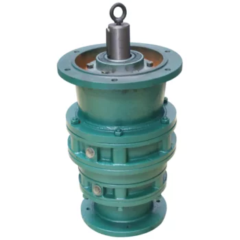
Distinguishing Features of Cycloidal GearboxesCycloidal gearboxes, also known as cycloidal drives or cycloidal reducers, possess distinct characteristics that set them apart from other types of gearboxes:
These distinguishing features contribute to the unique capabilities and benefits of cycloidal gearboxes in specific applications. | Customized Request |
|---|
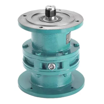
Industries Benefiting from Cycloidal Gearboxes
Cycloidal gearboxes find applications in various industries where their unique characteristics are advantageous:
- Robotics and Automation: Cycloidal gearboxes are widely used in robotic systems for their compact design, high torque capacity, and precise motion control.
- Material Handling: Industries such as logistics and warehousing benefit from cycloidal gearboxes in conveyor systems due to their ability to handle heavy loads and provide smooth and accurate movement.
- Manufacturing: Equipment used in manufacturing processes, such as packaging machines and printing presses, often incorporate cycloidal gearboxes for their reliability and precise positioning.
- Aerospace: In aerospace applications, cycloidal gearboxes can be found in satellite systems, where their compactness and high torque-to-weight ratio are crucial.
- Medical Devices: Cycloidal gearboxes are used in medical equipment like robotic surgery systems for their precise movement capabilities and space-saving design.
- Defense: Military applications, such as remotely operated vehicles and surveillance equipment, benefit from cycloidal gearboxes’ ability to handle rugged conditions and provide precise control.
These industries leverage the advantages of cycloidal gearboxes to enhance the performance and efficiency of their systems.


editor by CX 2023-08-22
China Best Sales B/X Series Cycloidal Pinwheel Planetary Gearbox for Belt Conveyor gearbox engine
Product Description
Technical parameters
| Model | Power P(kW) | ratio (i) |
Rotate speed N(RPM) |
Output torque T (N. m) |
| 09#-9# | 0.12 – 90 | 7 -650000 | 17-155 | top to 30000 |
Features
– Highly Standard Modular Designed
– Quality material ensures the product reliability
– High Strength,Compact Dimension
– Long Service Life
– Low Noise
– High Efficiency
– Large radial loading ability
– Axial load ability of up to 5% of radial load
Application examples
– Belt conveyor drives
– Bucket elevator drives
– Agitator drives
– Hoisting gear drives
– Travelling gear drives
– Paper machine drives
– Dryer drives
– Water screw drives
Installation
Plant
Office Block
Team
| Application: | Machinery, Industry |
|---|---|
| Hardness: | Soft Tooth Surface |
| Installation: | Horizontal Type |
| Layout: | Cycloidal |
| Gear Shape: | Bevel Gear |
| Step: | Single-Step |
| Customization: |
Available
| Customized Request |
|---|
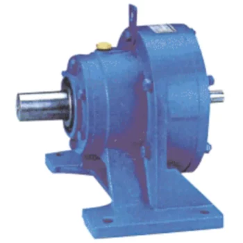
What is a Cycloidal Gearbox?
A cycloidal gearbox, also known as a cycloidal drive, is a type of gearing mechanism that utilizes the principle of cycloidal motion for power transmission. It consists of several components, including a high-speed input shaft, a set of cycloidal pins or rollers, and an outer stationary ring with lobed profiles.
The operation of a cycloidal gearbox involves a unique mechanism:
- Input Shaft: The high-speed input shaft is connected to the driving source, such as an electric motor. It transfers rotational motion to the cycloidal pins.
- Cycloidal Pins or Rollers: These pins or rollers are typically arranged around the input shaft in a circular pattern. As the input shaft rotates, the cycloidal pins also rotate, causing them to engage with the lobes on the outer stationary ring.
- Outer Stationary Ring: The outer ring has lobed profiles, and it remains stationary during operation. The lobes of the outer ring interact with the cycloidal pins or rollers, causing them to move in a unique motion known as epicycloidal or hypocycloidal motion.
The interaction between the cycloidal pins and the lobed profiles of the outer ring results in smooth and controlled motion transmission.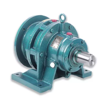
Patents Associated with Cycloidal Gearbox Designs
Throughout the history of cycloidal gearbox development, several patents have been filed for various designs and applications. Some notable 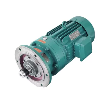
Materials Used in Manufacturing Cycloidal Gearboxes
Cycloidal gearboxes are constructed using a variety of materials to ensure durability, strength, and efficient operation. Some common materials used include:
- Steel: Steel is a popular choice due to its high strength and durability. It can withstand heavy loads and provides excellent wear resistance, making it suitable for industrial applications.
- Aluminum: Aluminum is chosen for its lightweight properties and corrosion resistance. It’s often used in applications where weight is a concern, such as aerospace and robotics.
- Cast Iron: Cast iron offers good heat dissipation and is known for its high resistance to wear and shock. It’s commonly used in heavy-duty applications that require high torque and strength.
- Alloys: Various alloy combinations can be used to enhance specific properties such as corrosion resistance, heat resistance, and strength.
- Plastics and Composites: In some cases, plastic or composite materials may be used, particularly in applications where low noise, lightweight construction, and corrosion resistance are essential.
The material selection depends on factors like the application’s torque, speed, environmental conditions, and desired performance characteristics. Each material offers a unique set of advantages, allowing cycloidal gearboxes to be customized to meet diverse industrial needs.
patents include:
- Harmonic Drive: Ralph B. Heath’s patent for the “Harmonic Drive” (US Patent 2,906,143), filed in 1957, is one of the most famous patents related to cycloidal gear systems. This patent introduced the concept of a high-precision reduction gear mechanism using flexible components.
- Cycloidal Drive Mechanism: A patent by James Watt for a “Cycloidal Drive Mechanism” (GB Patent 1812), dating back to the 18th century, is often cited as one of the early references to cycloidal motion and gears.
- Planetary Roller Transmission: US Patent 3,671,927 by C.F. Kafesjian and H. Blumenstock introduced a “Planetary Roller Transmission” in 1972, describing a cycloidal drive mechanism with planetary motion.
- Cycloidal Speed Reducer: A patent for a “Cycloidal Speed Reducer” (US Patent 5,588,583) was granted to Richard J. Pieprzak in 1996, focusing on an improved design of cycloidal gears for various applications.
These patents represent a small sample of the numerous innovations and designs related to cycloidal gear systems that have been patented over the years. Patents play a significant role in protecting and promoting innovation in the field of gearbox technology.
The mechanism provides advantages such as high torque capacity, compact size, and precise positioning capabilities.
Cycloidal gearboxes are widely used in various applications, including robotics, automation, packaging machinery, and other industrial systems where high torque, precision, and compact design are essential.


editor by CX 2023-08-17
China OEM 750W 25: 1 Compact and Lightweight Low Vibration Belt Conveyor Gearbox cycloidal gearbox manufacturers
Product Description
Product Description
750W 25:1 Compact and lightweight low vibration belt conveyor gearbox for 5 axis machining center developed and manufactured by WEITENSTAN together with German and ZheJiang technicians for many years.
High precision miniature cycloidal gearbox has the characteristics of smaller, ultra-thin, lightweight and high rigidity, anti-overload and high torque. With good deceleration performance, smooth operation and accurate positioning can be achieved. Integrated design, can be directly connected with the motor, to achieve high precision, high rigidity, high durability and other advantages. It is designed for high speed ratio, high geometric accuracy, low motion loss, large torque capacity and high stiffness applications. The compact design (minimum OD ≈40mm, currently the world’s smallest precision cycloidal pin-wheel reducer) allows it to be installed in limited Spaces.
Reducer drawings
Detailed Photos
Product Advantage
750W 25:1 Compact and lightweight low vibration belt conveyor gearbox advantages:
1, fine precision cycloidal structure
Ultra flat shape is achieved through differential reduction mechanism and thin cross roller bearing, contributing to the compact size of the equipment. The combination of small size and unmatched superior parameters achieves the best combination of performance, price and size (high cost performance).
2. Excellent accuracy (transmission loss ≤1 arcmin)
Through the complex meshing of precision cycloid gear and high precision roller pin, higher transmission accuracy is achieved while maintaining small size and high speed ratio.
3, high rigidity
Increase the mesh rate to disperse the load, so the rigidity is high.
4. High overload capacity
It maintains trouble-free operation under abnormally low noise and vibration conditions while ensuring excellent overturning and torsional stiffness parameters. Integrated axial radial cross roller bearings, high load capacity and overload capacity of the reducer, can ensure users to provide a variety of temperature range of applications.
5, the motor installation is simple
Electromechanical integration design, can be directly connected with the motor, any brand of motor can be installed directly, without adding any device.
6. Maintenance free
Seal grease to achieve maintenance free. No refueling, no mounting direction restrictions.
7, stable performance
The manufacturing process of high wear-resistant materials and high precision parts has been certified by ISO9000 quality system, which guarantees the reliable operation of the reducer.
Product Classification
WF Series
High Precision Miniature Reducer
WF series is a high precision micro cycloidal reducer with flange, which has a wide range of applications. This series of reducers includes precise reduction mechanisms and radial – axial roller bearings. The unique design allows load to act directly on the output flange or housing without additional bearings. WF series reducer is characterized by module design, can be installed through the flange motor and reducer, belongs to the motor directly connected reducer.
WFH Series
High Precision Miniature Reducer
WFH series is a hollow form of high precision miniature cycloidal reducer, wire, compressed air pipeline, drive shaft can be through the hollow shaft, non-motor direct connection type reducer. The WFH series is fully sealed, full of grease and includes precise deceleration mechanism and radial – axial roller bearings. The unique design allows load to be acted directly on the output flange or housing without additional bearings.
Product Parameters
| Size | reduction ratio | Rated output moment | Allowable torque of start and stop | Instantaneous allowable moment | Rated input speed | Maximum input speed | Tilt stiffness | Torsional stiffness | No-load starting torque | Transmission accuracy | Error accuracy | Moment of inertia | Weight | |
| Axis rotation | Shell rotation | Nm | Nm | Nm | rpm | rpm | Nm/arcmin | Nm/arcmin | Nm | arcmin | arcmin | kg-m² | kg | |
| WF07 | 21 | 20 | 15 | 30 | 45 | 3000 | 6000 | 6 | 1.1 | 0.12 | P1≤±1 P2≤±3 | P1≤±1 P2≤±3 | 0.52 | 0.42 |
| 41 | 40 | 0.11 | 0.47 | |||||||||||
| WF17 | 21 | 20 | 50 | 100 | 150 | 3000 | 6000 | 28 | 6 | 0.21 | P1≤±1 P2≤±3 | P1≤±1 P2≤±3 | 0.88 | 0.85 |
| 41 | 40 | 0.18 | 0.72 | |||||||||||
| 61 | 60 | 0.14 | 0.69 | |||||||||||
| WF25 | 21 | 20 | 110 | 220 | 330 | 3000 | 5500 | 131 | 24 | 0.47 | P1≤±1 P2≤±3 | P1≤±1 P2≤±3 | 6.12 | 2 |
| 31 | 30 | 0.41 | 5.67 | |||||||||||
| 41 | 40 | 0.38 | 4.9 | |||||||||||
| 51 | 50 | 0.35 | 4.56 | |||||||||||
| 81 | 80 | 0.31 | 4.25 | |||||||||||
| WF32 | 25 | 24 | 190 | 380 | 570 | 3000 | 4500 | 240 | 35 | 1.15 | P1≤±1 P2≤±3 | P1≤±1 P2≤±3 | 11 | 4.2 |
| 31 | 30 | 1.1 | 10.8 | |||||||||||
| 51 | 50 | 0.77 | 9.35 | |||||||||||
| 81 | 80 | 0.74 | 8.32 | |||||||||||
| 101 | 100 | 0.6 | 7.7 | |||||||||||
| WF40 | 25 | 24 | 320 | 640 | 960 | 3000 | 4000 | 377 | 50 | 1.35 | P1≤±1 P2≤±3 | P1≤±1 P2≤±3 | 13.2 | 6.6 |
| 31 | 30 | 1.32 | 12.96 | |||||||||||
| 51 | 50 | 0.92 | 11.22 | |||||||||||
| 81 | 80 | 0.81 | 9.84 | |||||||||||
| 121 | 120 | 0.72 | 8.4 | |||||||||||
Installation Instructions
Company Profile
Q: Speed reducer grease replacement time
A: When sealing appropriate amount of grease and running reducer, the standard replacement time is 20000 hours according to the aging condition of the grease. In addition, when the grease is stained or used in the surrounding temperature condition (above 40ºC), please check the aging and fouling of the grease, and specify the replacement time.
Q: Delivery time
A: Fubao has 2000+ production base, daily output of 1000+ units, standard models within 7 days of delivery.
Q: Reducer selection
A: Fubao provides professional product selection guidance, with higher product matching degree, higher cost performance and higher utilization rate.
Q: Application range of reducer
A: Fubao has a professional research and development team, complete category design, can match any stepping motor, servo motor, more accurate matching.
|
Shipping Cost:
Estimated freight per unit. |
To be negotiated |
|---|
| Application: | Motor, Machinery, Agricultural Machinery, Humanoid Robot |
|---|---|
| Hardness: | Hardened Tooth Surface |
| Installation: | Vertical Type |
| Customization: |
Available
| Customized Request |
|---|
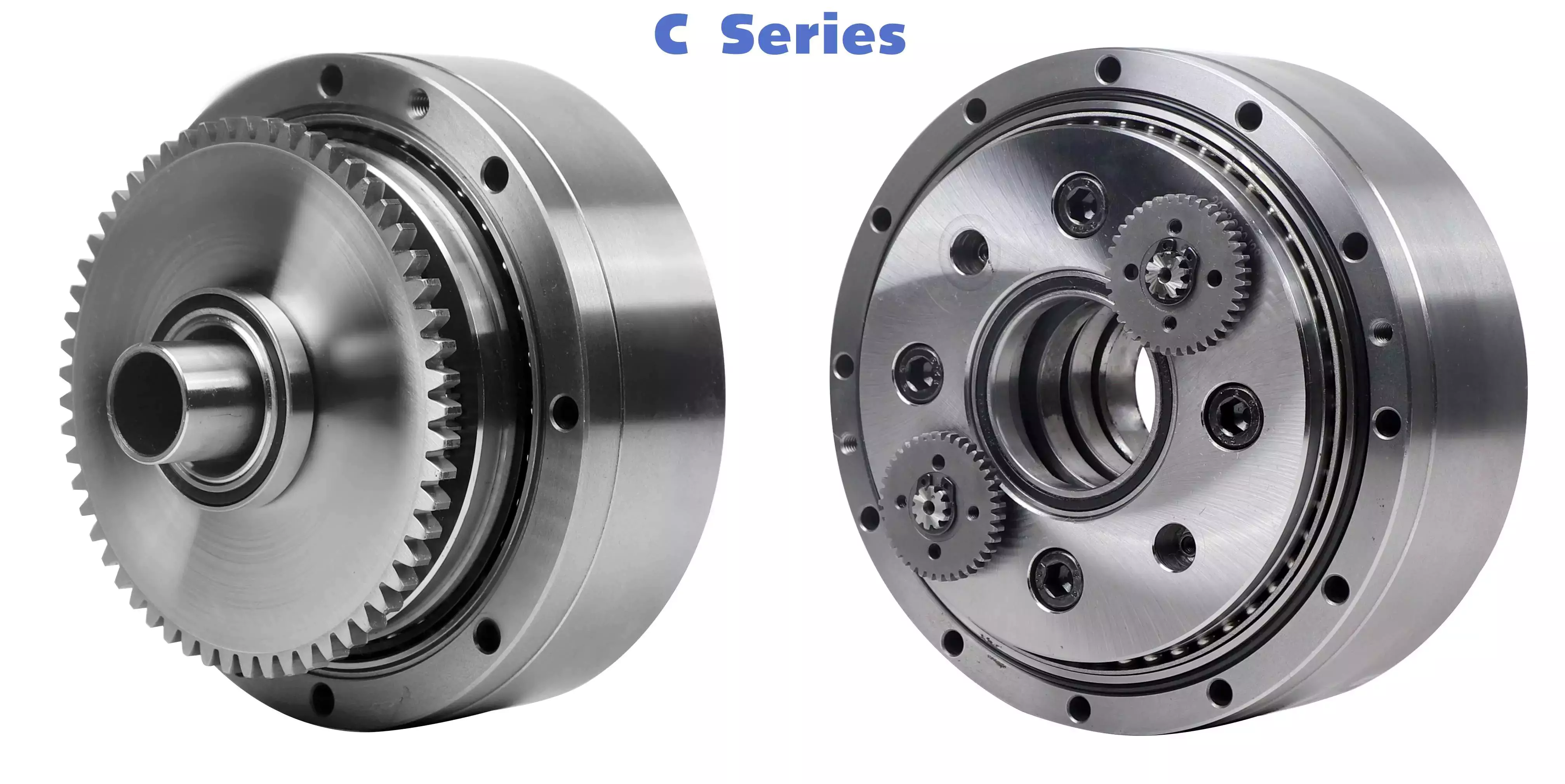
The Cyclonoidal Gearbox
Basically, the cycloidal gearbox is a gearbox that uses a cycloidal motion to perform its rotational movement. It is a very simple and efficient design that can be used in a variety of applications. A cycloidal gearbox is often used in applications that require the movement of heavy loads. It has several advantages over the planetary gearbox, including its ability to be able to handle higher loads and higher speeds.
Dynamic and inertial effects of a cycloidal gearbox
Several studies have been conducted on the dynamic and inertial effects of a cycloidal gearbox. Some of them focus on operating principles, while others focus on the mathematical model of the gearbox. This paper examines the mathematical model of a cycloidal gearbox, and compares its performance with the real-world measurements. It is important to have a proper mathematical model to design and control a cycloidal gearbox. A cycloidal gearbox is a two-stage gearbox with a cycloid disc and a ring gear that revolves around its own axis.
The mathematical model is made up of more than 1.6 million elements. Each gear pair is represented by a reduced model with 500 eigenmodes. The eigenfrequency for the spur gear is 70 kHz. The modally reduced model is a good fit for the cycloidal gearbox.
The mathematical model is validated using ABAQUS software. A cycloid disc was discretized to produce a very fine model. It requires 400 element points per tooth. It was also verified using static FEA. This model was then used to model the stiction of the gears in all quadrants. This is a new approach to modelling stiction in a cycloidal gearbox. It has been shown to produce results comparable to those of the EMBS model. The results are also matched by the elastic multibody simulation model. This is a good fit for the contact forces and magnitude of the cycloid gear disc. It was also found that the transmission accuracy between the cycloid gear disc and the ring gear is about 98.5%. However, this value is lower than the transmission accuracy of the ring gear pair. The transmission error of the corrected model is about 0.3%. The transmission accuracy is less because of the lower amount of elastic deformation on the tooth flanks.
It is important to note that the most accurate contact forces for each tooth of a cycloid gearbox are not smooth. The contact force on a single tooth starts with a linear rise and then ends with a sharp drop. It is not as smooth as the contact force on a point contact, which is why it has been compared to the contact force on an ellipse contact. However, the contact on an ellipse contact is still relatively small, and the EMBS model is not able to capture this.
The FE model for the cycloid disc is about 1.6 million elements. The most important part of the FE model is the discretization of the cycloid disc. It is very important to do the discretization of the cycloid gear disc very carefully because of the high degree of vibration that it experiences. The cycloid disc has to be discretized finely so that the results are comparable to those of a static FEA. It has to be the most accurate model possible in order to be able to accurately simulate the contact forces between the cycloid disc and the ring gear.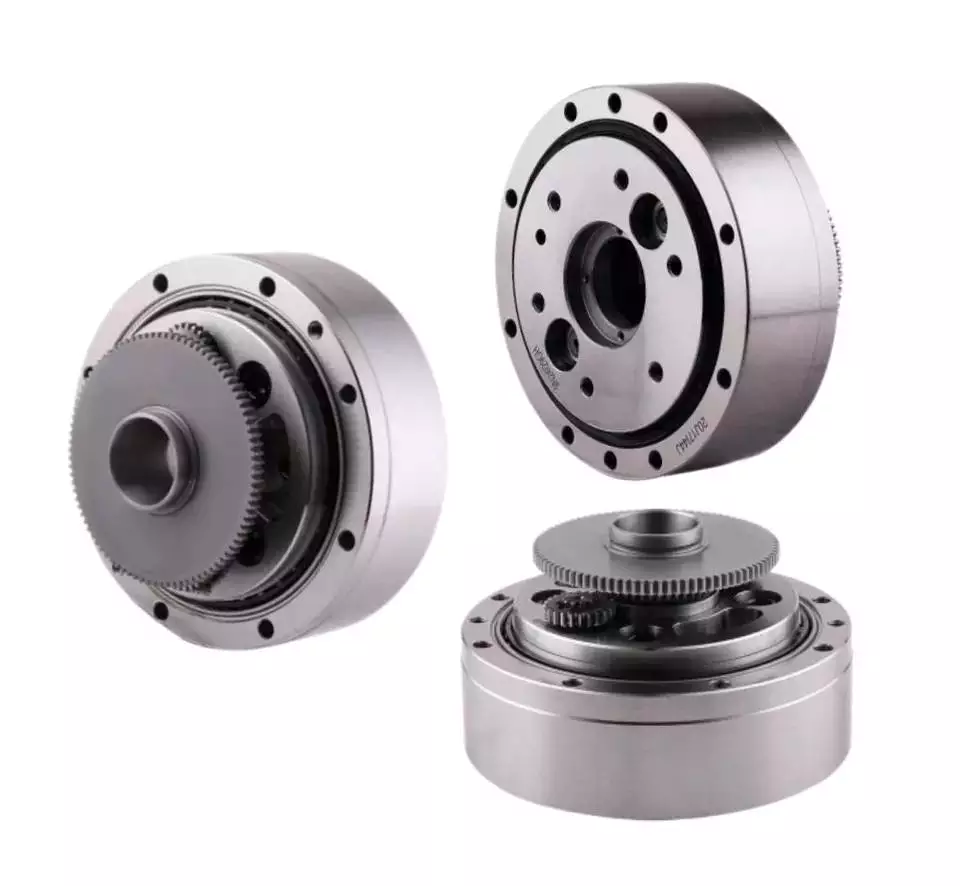
Kinematics of a cycloidal drive
Using an arbitrary coordinate system, we can observe the motion of components in a cycloidal gearbox. We observe that the cycloidal disc rotates around fixed pins in a circle, while the follower shaft rotates around the eccentric cam. In addition, we see that the input shaft is mounted eccentrically to the rolling-element bearing.
We also observe that the cycloidal disc rotates independently around the eccentric bearing, while the follower shaft rotates around an axis of symmetry. We can conclude that the cycloidal disc plays a pivotal role in the kinematics of a cycloidal gearbox.
To calculate the efficiency of the cycloidal reducer, we use a model that is based on the non-linear stiffness of the contacts. In this model, the non-linearity of the contact is governed by the non-linearity of the force and the deformation in the contact. We have shown that the efficiency of the cycloidal reducer increases as the load increases. In addition, the efficiency is dependent on the sliding velocity and the deformations of the normal load. These factors are considered as the key variables to determine the efficiency of the cycloidal drive.
We also consider the efficiency of the cycloidal reducer with the input torque and the input speed. We can calculate the efficiency by dividing the net torque in the ring gear by the output torque. The efficiency can be adjusted to suit different operating conditions. The efficiency of the cycloidal drive is increased as the load increases.
The cycloidal gearbox is a multi-stage gearbox with a small shaft oin and a big shaft. It has 19 teeth and brass washers. The outer discs move in opposition to the middle disc, and are offset by 180 deg. The middle disc is twice as massive as the outer disc. The cycloidal disc has nine lobes that move by one lobe per drive shaft revolution. The number of pins in the disc should be smaller than the number of pins in the surrounding pins.
The input shaft drives an eccentric bearing that is able to transmit the power to the output shaft. In addition, the input shaft applies forces to the cycloidal disk through the intermediate bearing. The cycloidal disk then advances in 360 deg/pivot/roller steps. The output shaft pins then move around in the holes to make the output shaft rotate continuously. The input shaft applies a sinusoidal motion to maintain the constant speed of the base shaft. This sine wave causes small adjustments to the follower shaft. The forces applied to the internal sleeves are a part of the equilibrium mechanism.
In addition, we can observe that the cycloidal drive is capable of transmitting a greater torque than the planetary gear. This is due to the cycloidal gear’s larger axial length and the ring gear’s smaller hole diameter. It is also possible to achieve a positive fit between the fixed ring and the disc, which is achieved by toothing between the fixed ring and the disc. The cycloidal disk is usually designed with a short cycloid to minimize unbalance forces at high speeds.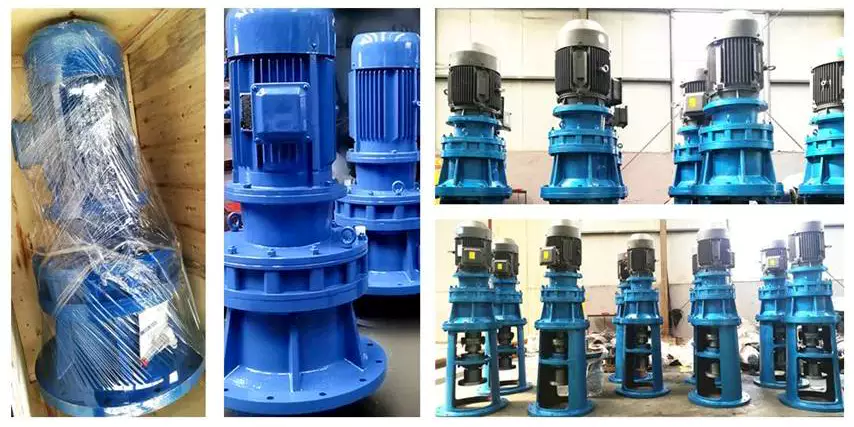
Comparison with planetary gearboxes
Compared to planetary gearboxes, the cycloidal gearbox has some advantages. These advantages include: low backlash, better overload capacity, a compact design, and the ability to perform in a wide range of applications. The cycloidal gearbox has become popular in the multi-axis robotics market. The gearbox is also increasingly used in first joints and positioners.
A cycloidal gearbox is a gearbox that consists of four basic components: a cycloid disk, an output flange, a ring gear, and a fixed ring. The cycloid disk is driven by an eccentric shaft, which advances in a 360deg/pivot/roller step. The output flange is a fixed pin disc that transmits the power to the output shaft. The ring gear is a fixed ring, and the input shaft is connected to a servomotor.
The cycloidal gearbox is designed to control inertia in highly dynamic situations. These gearboxes are generally used in robotics and positioners, where they are used to position heavy loads. They are also commonly used in a wide range of industrial applications. They have higher torque density and a low backlash, making them ideal for heavy loads.
The output flange is also designed to handle a torque of up to 500 Nm. Its rotational speed is lower than the planet gearbox, but its output torque is much higher. It is designed to be a high-performance gearbox, and it can be used in applications that need high ratios and a high level of torque density. The cycloid gearbox is also less expensive and has less backlash. However, the cycloidal gearbox has disadvantages that should be considered when designing a gearbox. The main problem is vibrations.
Compared to planetary gearboxes, cycloidal gearboxes have a smaller overall size and are less expensive. In addition, the cycloid gearbox has a large reduction ratio in one stage. In general, cycloidal gearboxes have single or two stages, with the third stage being less common. However, the cycloid gearbox is not the only type of gearbox that has this type of configuration. It is also common to find a planetary gearbox with a single stage.
There are several different types of cycloidal gearboxes, and they are often referred to as cycloidal speed reducers. These gearboxes are designed for any industry that uses servos. They are shorter than planetary gearboxes, and they are larger in diameter for the same torque. Some of them are also available with a ratio lower than 30:1.
The cycloid gearbox can be a good choice for applications where there are high rotational speeds and high torque requirements. These gearboxes are also more compact than planetary gearboxes, and are suitable for high-torque applications. In addition, they are more robust and can handle shock loads. They also have low backlash, and a higher level of accuracy and positioning accuracy. They are also used in a wide range of applications, including industrial robotics.

editor by CX 2023-05-08