Product Description
25r/m 0.8KW 27C BX RVC Series Collaborative Robot High Precision Cycloidal Gearbox For Agricultural Machinery
Model:27CBX-RVC
More Code And Specification:
| E series | C series | ||||
| Code | Outline dimension | General model | Code | Outline dimension | The original code |
| 120 | Φ122 | 6E | 10C | Φ145 | 150 |
| 150 | Φ145 | 20E | 27C | Φ181 | 180 |
| 190 | Φ190 | 40E | 50C | Φ222 | 220 |
| 220 | Φ222 | 80E | 100C | Φ250 | 250 |
| 250 | Φ244 | 110E | 200C | Φ345 | 350 |
| 280 | Φ280 | 160E | 320C | Φ440 | 440 |
| 320 | Φ325 | 320E | 500C | Φ520 | 520 |
| 370 | Φ370 | 450E | |||
Gear ratio And Specification
| E Series | C Series | ||
| Code | Reduction Ratio | New code | Monomer reduction ratio |
| 120 | 43,53.5,59,79,103 | 10CBX | 27.00 |
| 150 | 81,105,121,141,161 | 27CBX | 36.57 |
| 190 | 81,105,121,153 | 50CBX | 32.54 |
| 220 | 81,101,121,153 | 100CBX | 36.75 |
| 250 | 81,111,161,175.28 | 200CBX | 34.86 |
| 280 | 81,101,129,145,171 | 320CBX | 35.61 |
| 320 | 81,101,118.5,129,141,171,185 | 500CBX | 37.34 |
| 370 | 81,101,118.5,129,154.8,171,192.4 | ||
| Note 1: E series,such as by the shell(pin shell)output,the corresponding reduction ratio by 1 | |||
| Note 2: C series gear ratio refers to the motor installed in the casing of the reduction ratio,if installed on the output flange side,the corresponding reduction ratio by 1 | |||
Reducer type code
REV: main bearing built-in E type
RVC: hollow type
REA: with input flange E type
RCA: with input flange hollow type
Application:
Company Information
FAQ
Q: What’re your main products?
A: We currently produce Brushed Dc Motors, Brushed Dc Gear Motors, Planetary Dc Gear Motors, Brushless Dc Motors, Stepper motors, Ac Motors and High Precision Planetary Gear Box etc. You can check the specifications for above motors on our website and you can email us to recommend needed motors per your specification too.
Q: How to select a suitable motor?
A:If you have motor pictures or drawings to show us, or you have detailed specs like voltage, speed, torque, motor size, working mode of the motor, needed lifetime and noise level etc, please do not hesitate to let us know, then we can recommend suitable motor per your request accordingly.
Q: Do you have a customized service for your standard motors?
A: Yes, we can customize per your request for the voltage, speed, torque and shaft size/shape. If you need additional wires/cables soldered on the terminal or need to add connectors, or capacitors or EMC we can make it too.
Q: Do you have an individual design service for motors?
A: Yes, we would like to design motors individually for our customers, but it may need some mold developing cost and design charge.
Q: What’s your lead time?
A: Generally speaking, our regular standard product will need 15-30days, a bit longer for customized products. But we are very flexible on the lead time, it will depend on the specific orders.
Please contact us if you have detailed requests, thank you !
| Application: | Machinery, Robotic |
|---|---|
| Hardness: | Hardened Tooth Surface |
| Installation: | Vertical Type |
| Layout: | Coaxial |
| Gear Shape: | Cylindrical Gear |
| Step: | Double-Step |
| Customization: |
Available
| Customized Request |
|---|

Suitability of Cycloidal Gearboxes for High-Torque Applications
Cycloidal gearboxes are well-suited for high-torque applications due to their unique design and mechanical advantages. Here’s why they are suitable:
- Multiple Engagement Points: Cycloidal gearboxes have multiple teeth in contact at any given moment, distributing the load over a larger area. This reduces wear and stress on individual teeth, making them capable of handling high torque.
- High Load-Carrying Capacity: The design of the cycloidal mechanism, with its large number of pins and rollers, provides high load-carrying capacity. This makes them capable of transmitting significant torque without failure.
- Tight Tolerances: The precision and tight tolerances in the construction of cycloidal gearboxes ensure smooth and efficient power transmission even under heavy loads.
- Compact Design: Cycloidal gearboxes achieve high torque in a relatively compact size. This is particularly advantageous in applications where space is limited.
- High Gear Ratio: Cycloidal gearboxes can achieve high gear ratios, allowing them to convert lower input speeds into higher output torque, which is essential in high-torque applications.
These factors make cycloidal gearboxes a reliable choice for various high-torque applications across industries such as heavy machinery, robotics, material handling, and more.

Safety Measures for Operating Cycloidal Gear Systems
Operating cycloidal gear systems requires careful attention to safety to prevent accidents and ensure the well-being of operators and personnel. Here are important safety measures to consider:
- Training: Provide proper training to operators and maintenance personnel on the operation, maintenance, and potential hazards associated with cycloidal gear systems.
- Protective Equipment: Operators should wear appropriate personal protective equipment (PPE) such as gloves, safety glasses, and protective clothing.
- Lockout-Tagout: Implement lockout-tagout procedures to ensure that the system is de-energized and isolated before any maintenance or repair work begins.
- Regular Inspections: Conduct routine inspections of the gear system to identify any signs of wear, damage, or abnormalities that could compromise safety or performance.
- Lubrication: Follow the manufacturer’s recommendations for lubrication to maintain optimal performance and prevent overheating.
- Temperature Monitoring: Install temperature sensors or monitoring devices to detect any excessive heat buildup in the gearbox, which could indicate a potential issue.
- Proper Ventilation: Ensure that the area where the gear system operates is well-ventilated to prevent the accumulation of heat or harmful fumes.
- Emergency Stop: Install emergency stop buttons or switches that can immediately shut down the system in case of an emergency.
- Clearance Zones: Establish clear clearance zones around the gear system to prevent accidental contact with moving parts.
- Regular Maintenance: Follow a scheduled maintenance routine to keep the gear system in optimal working condition and address any potential safety concerns.
- Operator Awareness: Ensure that operators are aware of the gear system’s potential hazards and safe operating practices.
- Warning Signage: Clearly mark areas where the gear system operates with appropriate warning signs and labels.
- Emergency Procedures: Develop and communicate clear emergency procedures to respond to accidents, malfunctions, or other unexpected events.
Prioritizing safety in the operation and maintenance of cycloidal gear systems is essential to prevent injuries and maintain a safe working environment.

Industries Benefiting from Cycloidal Gearboxes
Cycloidal gearboxes find applications in various industries where their unique characteristics are advantageous:
- Robotics and Automation: Cycloidal gearboxes are widely used in robotic systems for their compact design, high torque capacity, and precise motion control.
- Material Handling: Industries such as logistics and warehousing benefit from cycloidal gearboxes in conveyor systems due to their ability to handle heavy loads and provide smooth and accurate movement.
- Manufacturing: Equipment used in manufacturing processes, such as packaging machines and printing presses, often incorporate cycloidal gearboxes for their reliability and precise positioning.
- Aerospace: In aerospace applications, cycloidal gearboxes can be found in satellite systems, where their compactness and high torque-to-weight ratio are crucial.
- Medical Devices: Cycloidal gearboxes are used in medical equipment like robotic surgery systems for their precise movement capabilities and space-saving design.
- Defense: Military applications, such as remotely operated vehicles and surveillance equipment, benefit from cycloidal gearboxes’ ability to handle rugged conditions and provide precise control.
These industries leverage the advantages of cycloidal gearboxes to enhance the performance and efficiency of their systems.


editor by CX 2023-10-20
China Best Sales Hardened Tooth Surface Agricultural Machinery CZPT Carton Nmrv Gearbox Robot cycloidal gear drive
Product Description
TaiBang Motor Industry Group Co., Ltd.
The main products is induction motor, reversible motor, DC brush gear motor, DC brushless gear motor, CH/CV big gear motors, Planetary gear motor ,Worm gear motor etc, which used widely in various fields of manufacturing pipelining, transportation, food, medicine, printing, fabric, packing, office, apparatus, entertainment etc, and is the preferred and matched product for automatic machine.
Taibang planetary gear motor is high energy efficiency,low noise,long service life,which is widely used in various industry.
Model Instruction
| GE | 090 | 571 | P2 |
| Reducer Series Code | External Diameter | Reduction Ratio | Reducer Backlash |
| GB:High Precision Square Flange Output
GBR:High Precision Right Angle Square Flange Output GE:High Precision Round Flange Output GER:High Precision Right Round Flange Output |
050:ø50mm 070:ø70mm 090:ø90mm 120:ø120mm 155:ø155mm 205:ø205mm 235:ø235mm 042:42x42mm 060:60x60mm 090:90x90mm 115:115x115mm 142:142x142mm 180:180x180mm 220:220x220mm |
571 means 1:10 | P0:High Precision Backlash
P1:Precison Backlash P2:Standard Backlash |
Main Technical Performance
| Item | Number of stage | Reduction Ratio | GB042 | GB060 | GB060A | GB090 | GB090A | GB115 | GB142 | GB180 | GB220 |
| Rotary Inertia | 1 | 3 | 0.03 | 0.16 | 0.61 | 3.25 | 9.21 | 28.98 | 69.61 | ||
| 4 | 0.03 | 0.14 | 0.48 | 2.74 | 7.54 | 23.67 | 54.37 | ||||
| 5 | 0.03 | 0.13 | 0.47 | 2.71 | 7.42 | 23.29 | 53.27 | ||||
| 6 | 0.03 | 0.13 | 0.45 | 2.65 | 7.25 | 22.75 | 51.72 | ||||
| 7 | 0.03 | 0.13 | 0.45 | 2.62 | 7.14 | 22.48 | 50.97 | ||||
| 8 | 0.03 | 0.13 | 0.44 | 2.58 | 7.07 | 22.59 | 50.84 | ||||
| 9 | 0.03 | 0.13 | 0.44 | 2.57 | 7.04 | 22.53 | 50.63 | ||||
| 10 | 0.03 | 0.13 | 0.44 | 2.57 | 7.03 | 22.51 | 50.56 | ||||
| 2 | 15 | 0.03 | 0.03 | 0.13 | 0.13 | 0.47 | 0.47 | 2.71 | 7.42 | 23.29 | |
| 20 | 0.03 | 0.03 | 0.13 | 0.13 | 0.47 | 0.47 | 2.71 | 7.42 | 23.29 | ||
| 25 | 0.03 | 0.03 | 0.13 | 0.13 | 0.47 | 0.47 | 2.71 | 7.42 | 23.29 | ||
| 30 | 0.03 | 0.03 | 0.13 | 0.13 | 0.47 | 0.47 | 2.71 | 7.42 | 23.29 | ||
| 35 | 0.03 | 0.03 | 0.13 | 0.13 | 0.47 | 0.47 | 2.71 | 7.42 | 23.29 | ||
| 40 | 0.03 | 0.03 | 0.13 | 0.13 | 0.47 | 0.47 | 2.71 | 7.42 | 23.29 | ||
| 45 | 0.03 | 0.03 | 0.13 | 0.13 | 0.47 | 0.47 | 2.71 | 7.42 | 23.29 | ||
| 50 | 0.03 | 0.03 | 0.13 | 0.13 | 0.44 | 0.44 | 2.57 | 7.03 | 22.51 | ||
| 60 | 0.03 | 0.03 | 0.13 | 0.13 | 0.44 | 0.44 | 2.57 | 7.03 | 22.51 | ||
| 70 | 0.03 | 0.03 | 0.13 | 0.13 | 0.44 | 0.44 | 2.57 | 7.03 | 22.51 | ||
| 80 | 0.03 | 0.03 | 0.13 | 0.13 | 0.44 | 0.44 | 2.57 | 7.03 | 22.51 | ||
| 90 | 0.03 | 0.03 | 0.13 | 0.13 | 0.44 | 0.44 | 2.57 | 7.03 | 22.51 | ||
| 100 | 0.03 | 0.03 | 0.13 | 0.13 | 0.44 | 0.44 | 2.57 | 7.03 | 22.51 |
| Item | Number of stage | GB042 | GB060 | GB060A | GB90 | GB090A | GB115 | GB142 | GB180 | GB220 | |
| Backlash(arcmin) | High Precision P0 | 1 | ≤1 | ≤1 | ≤1 | ≤1 | ≤1 | ≤1 | |||
| 2 | ≤3 | ≤3 | ≤3 | ≤3 | |||||||
| Precision P1 | 1 | ≤3 | ≤3 | ≤3 | ≤3 | ≤3 | ≤3 | ≤3 | ≤3 | ≤3 | |
| 2 | ≤5 | ≤5 | ≤5 | ≤5 | ≤5 | ≤5 | ≤5 | ≤5 | ≤5 | ||
| Standard P2 | 1 | ≤5 | ≤5 | ≤5 | ≤5 | ≤5 | ≤5 | ≤5 | ≤5 | ≤5 | |
| 2 | ≤7 | ≤7 | ≤7 | ≤7 | ≤7 | ≤7 | ≤7 | ≤7 | ≤7 | ||
| Torsional Rigidity(N.M/arcmin) | 1 | 3 | 7 | 7 | 14 | 14 | 25 | 50 | 145 | 225 | |
| 2 | 3 | 7 | 7 | 14 | 14 | 25 | 50 | 145 | 225 | ||
| Noise(dB) | 1,2 | ≤56 | ≤58 | ≤58 | ≤60 | ≤60 | ≤63 | ≤65 | ≤67 | ≤70 | |
| Rated input speed(rpm) | 1,2 | 5000 | 5000 | 5000 | 4000 | 4000 | 4000 | 3000 | 3000 | 2000 | |
| Max input speed(rpm) | 1,2 | 10000 | 10000 | 10000 | 8000 | 8000 | 8000 | 6000 | 6000 | 4000 | |
Noise test standard:Distance 1m,no load.Measured with an input speed 3000rpm
| Application: | Machinery, Agricultural Machinery, Automatic Machinery |
|---|---|
| Function: | Distribution Power, Change Drive Torque, Change Drive Direction, Speed Reduction |
| Layout: | Cycloidal |
| Hardness: | Hardened Tooth Surface |
| Installation: | Vertical Type |
| Step: | Double-Step |
| Samples: |
US$ 50/Piece
1 Piece(Min.Order) | |
|---|
| Customization: |
Available
| Customized Request |
|---|

The Basics of Designing a Cyclone Gearbox
Compared to conventional gearboxes, the cycloidal gearbox offers a number of advantages including a higher ratio of transmission, robustness against shock loads, and greater positioning accuracy. However, designing a cycloidal gearbox can be complicated. This article will discuss some of the basic design principles. In addition, it will cover topics such as size, position accuracy, and transmission ratios.
Basic design principles
Unlike a conventional ring gear, a cycloidal gearbox uses a cycloidal disc to provide torque multiplication. The output direction of the cycloidal gear disc is opposite to the rotation of the input shaft. This allows for more compact gear construction. It also allows for increased load capacity.
Cycloid drive kinematics can appear complex, but they are actually quite simple. Instead of rotating around the center of gravity like conventional gears, the cycloidal disc rotates around fixed pins. This provides a higher reduction ratio.
To reduce vibrations and noise, multiple cycloidal discs are used. This allows for uniform distribution of forces on the carrier pin devices. This also provides a better rotational balance. In addition, multiple cycloidal discs reduce the axial moment of the carrier pin devices.
The cycloidal gear disc is supported by a separate gear disc bearing. This design provides a low component count and reduces wear. This type of kinematics can also be used in an electric motor with a high power density.
The cycloidal gear disc provides a high reduction ratio, which allows for compact construction. Unlike a ring gear, the cycloidal disc has fewer teeth. It also provides a higher reduction ratio, which is advantageous for high rotational input speed applications.
Cycloid gear discs have cylindrical holes, which allow for carrier pin devices to protrude through them. This is useful because the carrier pin devices can roll along the inside wall of the cylindrical hole in the gear disc.
A load plate is also used to provide anchorage for external structures. This plate contains threaded screw holes arranged 15mm away from the center. It has a 9mm external diameter and a 3mm through hole.
Transmission ratios up to 300:1
cycloidal gearboxes are used in a wide range of applications, from machine tools to medical imaging devices. Compared to planetary gearboxes, they offer superior positioning accuracy, torsional stiffness, backlash, and fatigue performance.
Cycloid gearboxes are also capable of transmitting more torque than planetary gears. In addition, they have a lower Hertzian contact stress and higher overload protection. Cycloid gearboxes are able to provide transmission ratios up to 300:1 in a small package.
Cycloid gears also have lower backlash over extended periods, making them an ideal choice for applications with critical positioning accuracy. Cycloid gearboxes also have good wear resistance, as well as low friction. Cycloid gears are lightweight and have good torsional stiffness, making them ideal for applications with heavy loads.
Cycloid gearboxes have several different designs. They can provide transmission ratios up to 300:1 without the need for additional pre-stages. Cycloid gears also require more accurate manufacturing processes than involute gears. Cycloid gearboxes can also be used for applications that require high power consumption, and can withstand shock loads.
Cycloid gearboxes can be adapted to fit most common servomotors. They have a modular design, all-round corrosion protection, and easy installation. Cycloid gears have a radial clamping ring, which reduces inertia by up to 39%.
CZPT Precision Europe GmbH, a subsidiary of CZPT Group, has developed an innovative online configurator to simplify the configuration of gearboxes. CZPT cycloidal gearheads are precision-built, robust, and reliable. They have a two-stage reduction principle, which minimises vibration and provides even force distribution.
Cycloid gears are capable of providing transmission ratios from 30:1 to 300:1. Cycloid gearboxes can achieve high gear ratios because they require fewer moving parts, and they have a low backlash.
Robustness against shock loads
Unlike conventional gearboxes that are easily damaged by shock loads, the cycloidal gearbox is extremely robust. It is a versatile solution that is ideally suited for handling equipment, food manufacturing, and machine tools.
The mechanical construction of a cycloidal gearbox consists of several mechanical components. These include cycloidal wheels, bearings, transformation elements, and needles. In addition, it has high torsional stiffness and tilting moment. It is also accompanied by highly nonlinear friction characteristic.
In order to assess the robustness of the cycloidal gearbox against shock loads, a mathematical model was developed. The model was used to calculate the stress distribution on the cycloid disc. This model can be used as a basis for more complex mechanical models.
The model is based on new approach, which allows to model stiction in all quadrants of the cycloid gear. In addition, it can be applied to actuator control.
The mathematical model is presented together with the procedure for measuring the contact stress. The results are compared to the measurement performed in the real system. The model and the measurement are found to be very close to each other.
The model also allows for the analysis of different gear profiles for load distribution. In addition, it is possible to analyze contact stresses with different geometric parameters. The mesh refinement along the disc width helps to ensure an even distribution of contact forces.
The stiction breakaway speed is calculated to the motor side. The non-zero current is then derived to the input side of the gearbox. In addition, a small steady phase is modeled during the speed direction transition. The results of the simulation are compared to the measurement. The results show that the model is extremely accurate.
Positioning accuracy
Getting the correct positioning accuracy from a cycloidal gearbox is no small feat. This is because the gears are compact, and the clearances are relatively small. This means you can expect a lot of torque from your output shaft. However, this is only part of the picture. Other concerns, such as backlash, kinematic error, and loading are all important considerations.
Getting the best possible positioning accuracy from a cycloidal gearbox means choosing a reducer that is well-made and correctly configured. A properly-selected reducer will eliminate repeatable inaccuracies and provide absolute positioning accuracy at all times. In addition, this type of gearbox offers several advantages over conventional gearboxes. These include high efficiency, low backlash, and high overload protection.
Getting the correct positioning accuracy from a gearbox also involves choosing a supplier that knows what it is doing. The best vendors are those who have experience with the product, offer a wide variety, and provide support and service to ensure the product is installed and maintained correctly. Another consideration is the manufacturer’s warranty. A reputable manufacturer will offer warranties for the gearbox. The aforementioned factors will ensure that your investment in a cycloidal gearbox pays off for years to come.
Getting the correct positioning accuracy from your cycloidal gearbox involves choosing a manufacturer that specializes in this type of product. This is particularly true if you are involved in robotics, automated painting, or any other industrial process that requires the best possible accuracy. A good manufacturer will offer the latest technology, and have the expertise to help you find the best solution for your application. This will ensure your product is a success from start to finish.
Size
Choosing the right size of cycloidal gearbox is important for its efficient operation. However, it is not a simple task. The process involves complex machining and requires the creation of many parts. There are different sizes of cycloidal gearboxes, and a few basic rules of thumb can help you choose the right size.
The first rule of thumb for choosing the right size of cycloidal gearboxes is to use a gearbox with the same diameter of the input shaft. This means that the gearbox must be at least 5mm thick. The cycloid will also require a base and a bearing to hold the driveshaft in place. The base should be large enough to house the pins. The bearing must be the same size as the input shaft.
The next rule of thumb is to have a hole in the cycloid for the output shaft. In this way, the output will be back-drivable and has low backlash. There should be at least four to six output holes. The size of the holes should be such that the centerline of the cycloid is equal to the size of the center of the bearing.
Using a Desmos graph, you can then create the gear parameters. The number of pins should be equal to the number of teeth in the cycloidal gear, and the size of the pins should be twice the size of the gear. The radius of the pins should be equal to the value of C from Desmos, and the size of the pin circle should be equal to the R value.
The final rule of thumb is to ensure that the cycloid has no sharp edges or discontinuities. It should also have a smooth line.

editor by CX 2023-05-06
China 220BX REA Series Agricultural Machinery High Precision Cycloidal Gearbox with Flange components of gearbox
Product Description
220BX REA Series Agricultural Machinery High Precision Cycloidal Gearbox with Flange
Model:220BX-REA-35
More Code And Specification:
| E series | C series | ||||
| Code | Outline dimension | General model | Code | Outline dimension | The original code |
| 120 | Φ122 | 6E | 10C | Φ145 | 150 |
| 150 | Φ145 | 20E | 27C | Φ181 | 180 |
| 190 | Φ190 | 40E | 50C | Φ222 | 220 |
| 220 | Φ222 | 80E | 100C | Φ250 | 250 |
| 250 | Φ244 | 110E | 200C | Φ345 | 350 |
| 280 | Φ280 | 160E | 320C | Φ440 | 440 |
| 320 | Φ325 | 320E | 500C | Φ520 | 520 |
| 370 | Φ370 | 450E | |||
Gear ratio And Specification
| E Series | C Series | ||
| Code | Reduction Ratio | New code | Monomer reduction ratio |
| 120 | 43,53.5,59,79,103 | 10CBX | 27.00 |
| 150 | 81,105,121,141,161 | 27CBX | 36.57 |
| 190 | 81,105,121,153 | 50CBX | 32.54 |
| 220 | 81,101,121,153 | 100CBX | 36.75 |
| 250 | 81,111,161,175.28 | 200CBX | 34.86 |
| 280 | 81,101,129,145,171 | 320CBX | 35.61 |
| 320 | 81,101,118.5,129,141,171,185 | 500CBX | 37.34 |
| 370 | 81,101,118.5,129,154.8,171,192.4 | ||
| Note 1: E series,such as by the shell(pin shell)output,the corresponding reduction ratio by 1 | |||
| Note 2: C series gear ratio refers to the motor installed in the casing of the reduction ratio,if installed on the output flange side,the corresponding reduction ratio by 1 | |||
Reducer type code
REV: main bearing built-in E type
RVC: hollow type
REA: with input flange E type
RCA: with input flange hollow type
Application:
Company Information
FAQ
Q: What’re your main products?
A: We currently produce Brushed Dc Motors, Brushed Dc Gear Motors, Planetary Dc Gear Motors, Brushless Dc Motors, Stepper motors, Ac Motors and High Precision Planetary Gear Box etc. You can check the specifications for above motors on our website and you can email us to recommend needed motors per your specification too.
Q: How to select a suitable motor?
A:If you have motor pictures or drawings to show us, or you have detailed specs like voltage, speed, torque, motor size, working mode of the motor, needed lifetime and noise level etc, please do not hesitate to let us know, then we can recommend suitable motor per your request accordingly.
Q: Do you have a customized service for your standard motors?
A: Yes, we can customize per your request for the voltage, speed, torque and shaft size/shape. If you need additional wires/cables soldered on the terminal or need to add connectors, or capacitors or EMC we can make it too.
Q: Do you have an individual design service for motors?
A: Yes, we would like to design motors individually for our customers, but it may need some mold developing cost and design charge.
Q: What’s your lead time?
A: Generally speaking, our regular standard product will need 15-30days, a bit longer for customized products. But we are very flexible on the lead time, it will depend on the specific orders.
Please contact us if you have detailed requests, thank you !
| To Be Negotiated | 1 Piece (Min. Order) |
###
| Application: | Machinery, Robotic |
|---|---|
| Hardness: | Hardened Tooth Surface |
| Installation: | Vertical Type |
| Layout: | Coaxial |
| Gear Shape: | Cylindrical Gear |
| Step: | Double-Step |
###
| Customization: |
Available
|
|---|
###
| E series | C series | ||||
| Code | Outline dimension | General model | Code | Outline dimension | The original code |
| 120 | Φ122 | 6E | 10C | Φ145 | 150 |
| 150 | Φ145 | 20E | 27C | Φ181 | 180 |
| 190 | Φ190 | 40E | 50C | Φ222 | 220 |
| 220 | Φ222 | 80E | 100C | Φ250 | 250 |
| 250 | Φ244 | 110E | 200C | Φ345 | 350 |
| 280 | Φ280 | 160E | 320C | Φ440 | 440 |
| 320 | Φ325 | 320E | 500C | Φ520 | 520 |
| 370 | Φ370 | 450E | |||
###
| E Series | C Series | ||
| Code | Reduction Ratio | New code | Monomer reduction ratio |
| 120 | 43,53.5,59,79,103 | 10CBX | 27.00 |
| 150 | 81,105,121,141,161 | 27CBX | 36.57 |
| 190 | 81,105,121,153 | 50CBX | 32.54 |
| 220 | 81,101,121,153 | 100CBX | 36.75 |
| 250 | 81,111,161,175.28 | 200CBX | 34.86 |
| 280 | 81,101,129,145,171 | 320CBX | 35.61 |
| 320 | 81,101,118.5,129,141,171,185 | 500CBX | 37.34 |
| 370 | 81,101,118.5,129,154.8,171,192.4 | ||
| Note 1: E series,such as by the shell(pin shell)output,the corresponding reduction ratio by 1 | |||
| Note 2: C series gear ratio refers to the motor installed in the casing of the reduction ratio,if installed on the output flange side,the corresponding reduction ratio by 1 | |||
The Different Types of Gearboxes
There are many different types of gearboxes. Some brands have more than one type. In this article, we’ll discuss the planetary gearbox, the worm reduction gearbox, the shaft mounted gearbox, and the one speed gearbox. This article will also help you determine which type of gearbox is best for your vehicle. And don’t worry if you don’t know the terminology yet. We’ll explain each type in detail so that you know what you’re getting yourself into.
Planetary gearbox
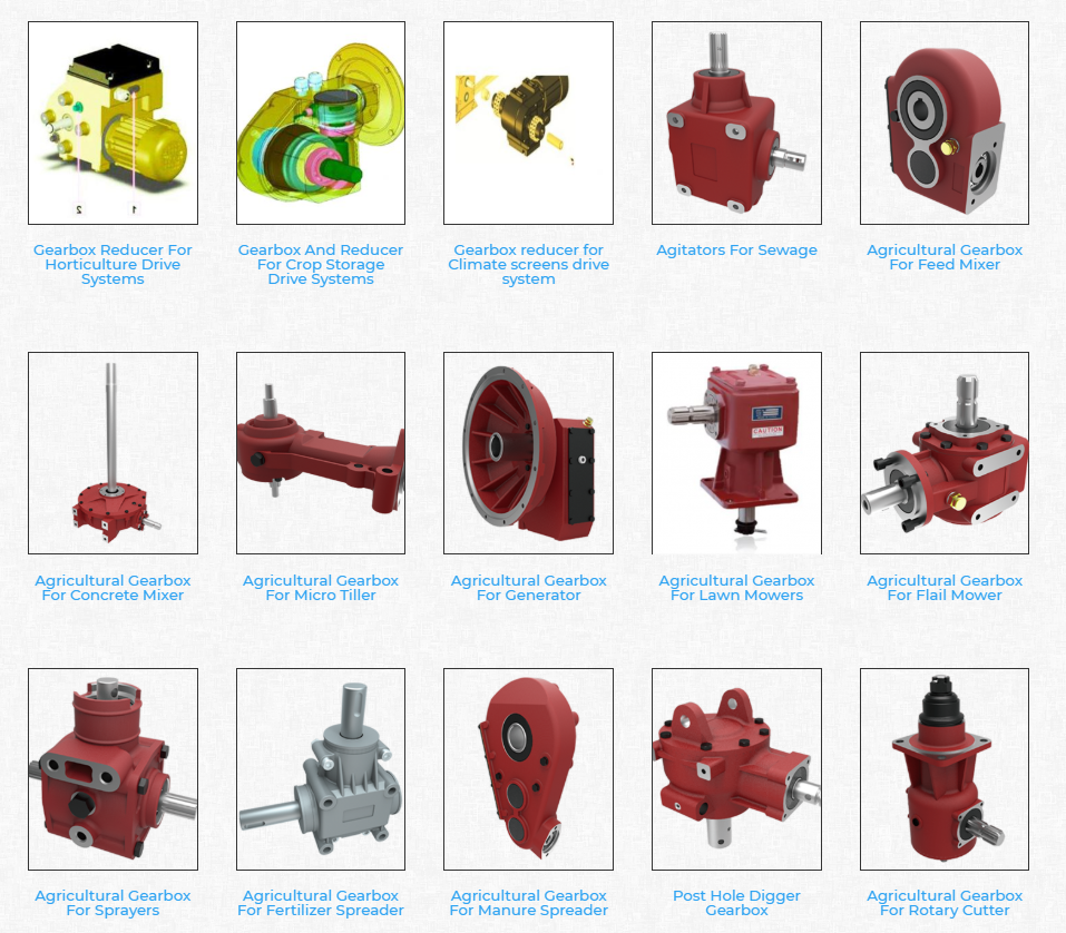
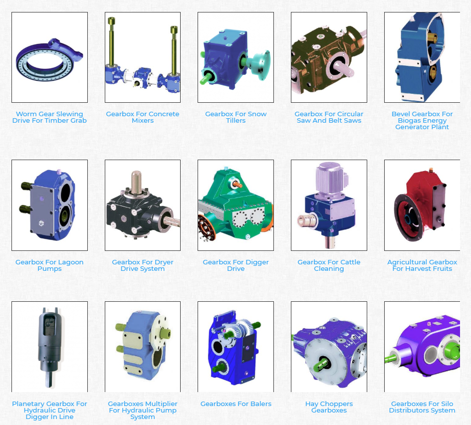
Planetary gears have many advantages. The multiple gears in a planetary gearbox mesh simultaneously during operation. As such, they provide high efficiency and transmit high transmittable torque. These gears are widely used in various industries and are resistant to high shock loads and demanding conditions. CZPT is one of the companies that offer planetary gearboxes. Its products do not require special tools for assembly, and its scalable design minimizes safety stock.
Among the numerous benefits of planetary gearing is its compactness and lightweight. As such, it is suitable for wide applications with space and weight constraints. However, to truly appreciate its benefits, it is necessary to understand its mechanisms. Here are some of the most common details about planetary gearing:
The planetary gearbox has two mounted gears: an input shaft and an output shaft. Each gear has multiple teeth that are attached to a carrier and rotate with the input shaft. The carrier is connected to the output shaft. A planetary gear is mounted on both gears via a carrier. The carrier rotates in order to drive the planetary gear. The sun gear is often the input gear. The other gear is called the outer gear.
Planetary gearboxes are highly customizable. The size, mounting, and housing options vary, as do the reduction ratios and input speeds. Different types can be manufactured for different applications and include options such as electrical or mechanical preload. The final design of a planetary gearbox can be highly customized, based on the specifications of the application. By combining engineering excellence and ongoing innovation, planetary gearboxes provide years of trouble-free operation.
A planetary gearbox can be either an electric motor or a manual one. The latter has more features than the former, and can be used in applications where space is an issue. The primary features of a planetary gearbox include its backlash, torque, and ratio. Secondary features include noise, corrosion resistance, and construction. A planetary gearbox is a highly versatile gearbox that can drive anything from simple machinery to advanced electrical systems.
Worm reduction gearbox
The global worm reduction gearbox market report compiles key insights from the industry to help you improve your business strategy. This report will help you create a comprehensive business document that will enhance your company’s competitive edge. To obtain this report, visit our website now! Read our latest report to find out what you can expect from the global worm reduction gearbox market. Alternatively, request a sample copy for more details. Here is a sneak peek of the report:
Worm gears are made with different thread counts and are usually not matched with the CZPT standard. In general, a single thread worm should be used with a single thread worm. Worm gears have either right or left threads, and their thread count will be different as well. This type of gear is used to reduce the speed of a rotating shaft. The speed reduction ratio will be about 50 percent if the worms have the same thread count as the CZPT gears.
The standard gear set transfers power at the peak load point of a tooth, called the pitchline. The worm gear moves slowly against the wheel’s metal surface. The worm gear is also more complex than the standard gear because the worm is sliding rather than rolling. Worm gears are hard to lubricate. Moreover, the sliding contact between the gear and worm increases the complexity of the gear set. They can be a great solution for applications where noise is a significant factor.
The axial pitch and circular pitch of the worm are equal. The ratio of these two indices determines the speed of transmission. For a worm reduction gearbox to work, the axial pitch and the circular pitch must match. The pitch angle of a worm can either be left-handed or right-handed. The lead of a worm is the distance one thread travels in one revolution. The lead angle is the angle tangent to the thread helix of the cylinder’s pitch. When a worm mesh is reversed, the majority of the mesh will be on the receding arc.
Worm gears generate more heat than their counterparts, so it is important to choose a worm reduction gearbox carefully. You will want to choose the material and amount of lubricating oil carefully. Worm gears are generally made of tin bronze. The paired worms are hardened to HRC45-55. In general, they are durable, lasting up to ten years. But they will wear out – and they wear out – so you may want to consider some other factors.
Shaft-mounted gearbox
Shaft-mounted gearboxes are designed for a variety of mining and quarry applications. Their high reliability and low maintenance make them an excellent choice in these types of applications. Shaft-mounted gearboxes also feature an optional backstop device that prevents the unit from rotating in one direction. This makes them an excellent choice for applications where alignment accuracy is an issue. Here are some of the benefits of using a shaft-mounted gearbox:
Shaft-mounted gearboxes are typically constructed of aluminium, and come in sizes ranging from 050 to 125. They feature a variety of reduction ratios and ensure optimum efficiency in all operating conditions. New S series sizes, 140 and 150, extend the application range of shaft-mounted gearmotors. They are both backed by a two-year warranty. For even greater peace of mind, Shaft-mounted gearboxes are available with a range of warranty options.
The most common applications for a Shaft-mounted gearbox include traction-driven applications where a low-speed shaft is required for operation. They also are suitable for applications without a foundation, where the motor is mounted next to the reducer. To prevent the gear drive from rotating, a torque arm is attached between the motor and the shaft. Small-sized shaft-mounted gear drives are usually made without motor mount kits, which can make them an excellent choice for conveying light loads.
Another important feature of a Shaft-mounted gearbox is its mounting position. The reduced motion through the drive is redirected through the shaft, creating additional forces. These additional forces can affect the performance of the gearbox, causing vibrations and noise. Consequently, it is important to replace worn or damaged belts on a regular basis. Further, shaft-mounted gearboxes can be affected by problems with other components and amplify vibrations.
1 speed gearbox
CZPT Group Components produces one speed gearboxes. These transmissions are produced in the CZPT Group’s Kassel plant. They are compact and robust, and are designed for easy integration. The Bosch Rexroth GD1 one-speed gearbox is easy to install horizontally or vertically. The Plug and Drive system integrates the gearbox with the existing cooling system. There are many other benefits to this gearbox.
With an ID.3 electric drive motor, the maximum torque is delivered at 16,000 rpm. This single-speed transmission offers high power density and excellent noise-reduction, making it ideal for electric vehicles. The e-drive motor is extremely quiet and requires precision manufacturing. The e-drive motor also enables a wide range of driving conditions. It can reverse when needed, and reaches its maximum speed at 16,000.
The single-speed gearbox is a standard feature on most electric vehicles. Some electric vehicles, such as the Porsche Taycan, will be equipped with a two-speed gearbox. This gearbox offers more top speed and range, but it is more complex than a standard single-speed gearbox. CZPT doesn’t need to add complexity to its electric vehicles. After all, a 355 horsepower family wagon is not likely to need a dual-speed gearbox.
In addition to simplifying the transmission, the patent claims also address improvements in structural design. Fig. 5 shows a schematic representation of a transmission 50′, wherein gear sets Z1 and Z4 are exchanged between partial transmissions. This switch matrix also reflects the synchronized gears and lastshelf gears. Hydraulically betatigte Lamellenkupplungen (HBA) also form a last-shelf gear.
Another advantage of the patent claim is that it offers numerous functional freedoms, which is especially valuable in the design of an automobile. One of the patent claims identifies a tosatzlicher middle gear that allows a driver to switch between second and third gears, with a single gearbox. In a conventional one-speed transmission, the tosatzlicher middle gear is attached to the second and first part gearbox. The latter has a second and third gear.
editor by czh 2022-11-28
Best China manufacturer & factory agricultural in Basel Switzerland machinery spline tiller cross joint cardan pto shaft with CE With high quality best price

We also can design and style and make non-standard products to meet customers’ specific specifications.
Overview
Quick Details
- Warranty:
-
one.5 a long time
- Applicable Industries:
-
Manufacturing Plant
- Soon after Warranty Provider:
-
On the web assist
- EPG specializing in the manufacture of rotocultivator ploughshares and other non-standardized farm machinery chopping tools. Local Service Location:
-
None
- Showroom Location:
-
Italy
- Kind:
-
Shafts
- Use:
-
Tractors
- Area of Origin:Zhejiang, China
- Brand name Identify:
-
OEM
- Neighborhood Service Location:
-
Italy
- Our PTO drive shafts enable the person simple maintenance. The greasing nipples on common crosses are positioned under angle to allow the consumer better accessibility. Easier obtain is also possible since of the flexible cone. We listened to the wishes of our consumers and positioned the greasing nipple at vast-angle PTO’s into the cross bearing. The other novelty, we introduced with vast-angle PTO drive shafts is in line greasing. We wished to in addition simplify the servicing and lengthen the lifespan of joints. certificate:
-
CE
- Content:
-
Metallic
- plastic guard:
-
YWBSYSBW tractor pto shaft
- purpose:
-
transmit energy tractor pto shaft
- spline:
-
1 3/8 Z6/Z21 tractor pto shaft
Supply Ability
- Offer Potential:
- 10000 Piece/Pieces for every Thirty day period tractor pto shaft
Packaging & Shipping and delivery
- Packaging Specifics
- carton/iron crate tractor pto shaft
- Port
- ningbo or shanghai
On the web Customization
Merchandise Details
Item Info

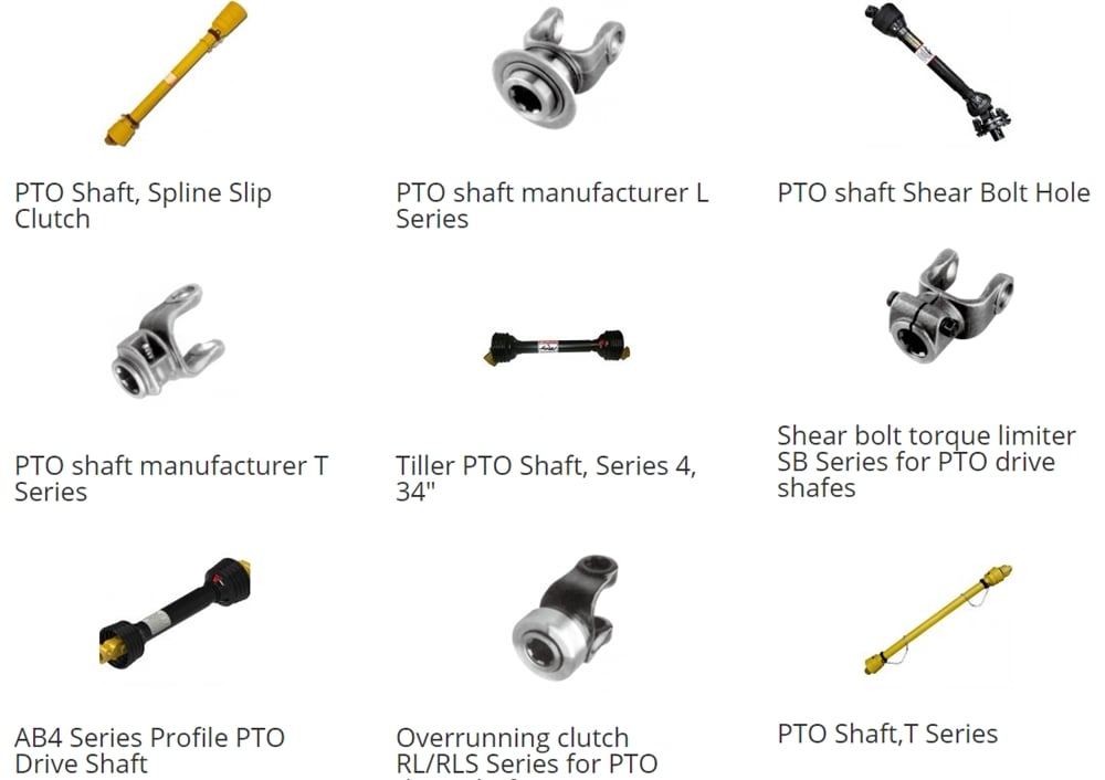
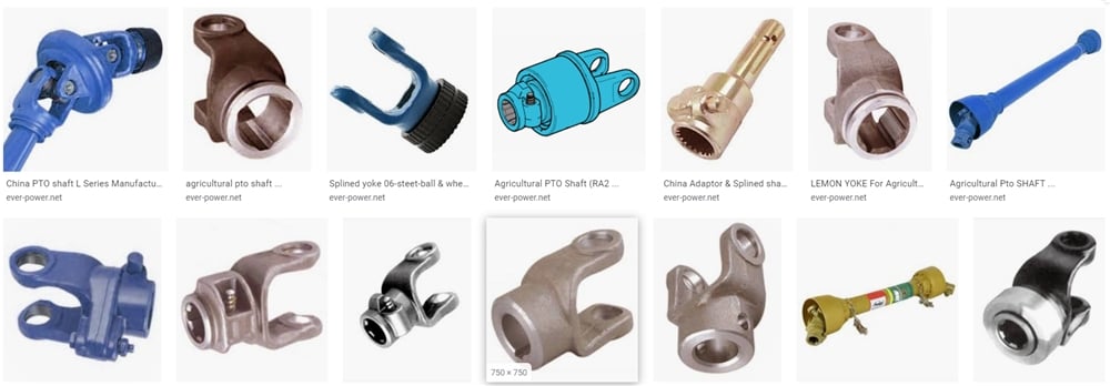
PTO Shaft
The energy take-off (PTO) is a innovative mechanism, enabling implements to draw vitality from the motor and transmit it to an additional software. It works as a mechanical gearbox which can be mounted on the vehicle’s transmission.
The power take-off shaft (PTO shaft) is a essential element, created and made for constant large-obligation use. A excellent PTO shaft must be strong sufficient to bear the torsion and shear stress and reduce vibration.
Setforge, the forging subsidiary of Ever-Power Team, manufactures chilly extruded PTO shafts for all sorts of agriculture vehicles. Our PTO shafts supply fantastic dependability and toughness for the duration of day-to-day use.
EP Group has been internationally identified as a dependable international supplier. Our condition-of-the-art producing procedure and experienced engineers ensure the prime-high quality of all Farinia parts.
| After Warranty Support | Video clip technical assist |
| Relevant Industries | Production Plant |
| Neighborhood Service Location | Italy |
| Showroom Place | Italy |
| Warranty | 1.5 a long time |
| Kind | Shafts |
| Use | Tractors |
| Place of Origin | China |
| China | Zhejiang |
| Brand Name | EPG |
| certification | CE |
| Substance | Metal |
| plastic guard | YWBSYSBW tractor pto shaft |
| perform | transmit power tractor pto shaft |
| spline | 1 3/8 Z6/Z21 tractor pto shaft |
Product Screen
Solution Display
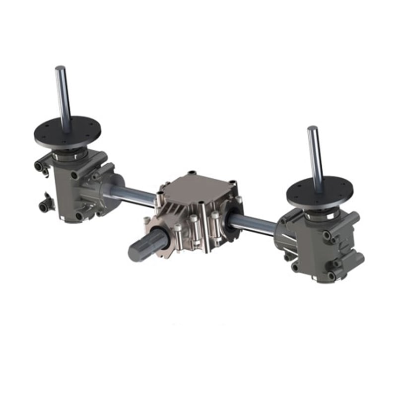
L sequence aluminium …

CAT 23 Fast Hitch
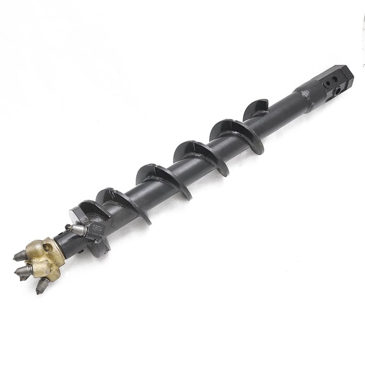
6″ Rock Auger
CompanyInfo
Company Profile
At any time-Electricity Group
EPG have large-tech machinery and take a look at products. We can generate entire world class substantial precision goods.
Certifications
Certifications
Cargo & Payment

Our Rewards
A: Your inquiry relevant to our goods or charges will be replied in 24 several hours.
B: Protection of your product sales region, tips of design and style and all your personal data.
C: Ideal good quality and aggressive cost.
……
faq
FAQ
Worm gears are typically created by hobbing with a hob or chopping instrument extremely related to the worm that the gear mates with. The worm may be turned, hobbed, milled, or floor.
1) How can I location purchase?
A: You can get in touch with us by e mail about your buy information, or spot get on line.
2) How can I pay you?
A: Right after you validate our PI, we will request you to pay out. T/T (HSBC financial institution) and Paypal, Western Union are the most typical approaches we are utilizing.
……