Product Description
Product Advantages
|
F Series Gearbox Reducer |
|
|
Product name |
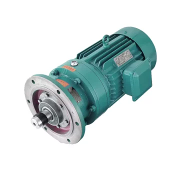
F series of the gearbox hollow shaft model F107 oil seal transmission gearbox reducer reduction |
|
Warranty |
1 years |
|
Applicable Industries |
Manufacturing Plant |
|
Weight (KG) |
50KG |
|
Customized support |
OEM |
|
Gearing Arrangement |
Helical |
|
Output Torque |
1.8-2430N.M |
|
Input Speed |
1440, 2800,960,750 |
|
Output Speed |
0.5 to 200 |
|
Place of Origin |
China |
|
Product name |
F Series Parallel Shaft Gearbox Reducer |
|
Application |
Hardened Tooth Surface |
|
Installation |
Horizontal Type |
|
Layout |
Coaxial |
|
Gear Shape |
Helical |
|
Production Capacity |
800-1500PCS /Month |
|
Type |
Gear Reduction Motor |
|
Color |
Blue,Sliver or Customized |
|
Packing |
Wooden Box |
Six advantages
F series Parallel Shaft Helical Gear Reducer
Helical gear hard tooth surface structure, 2 / 3 gear combinations can be selected to achieve the required speed ratio, with reinforced cast iron shell, high bearing capacity, can be matched with different types of motors, small size, light weight, large
torque, stable operation and low noise.
–Modular design, wide transmission ratio coverage, fine and reasonable distribution; Force reducer
–There are 11 types of frame specifications from F.27-F.157, and the transmission power range is 0.12KW-200KW;
–The shape design is suitable for omnidirectional universal installation configuration;
–The transmission is relatively accurate, covering the range of 3.77-281.71, and can be selected as required;
–The gear is grinded by high-precision gear grinding machine, with balanced transmission, low noise, and interstage efficiency of 98%;
–The transmission ratio of the F.R.reducer is extended to 31431, which is specially designed for special low-speed occasions
Editing and broadcasting of main materials
–Box: cast iron;
–Gear: low carbon alloy steel, carbonitriding treatment (after fine grinding, keep the tooth surface hardness of 60HRC, hard layer thickness>0.5mm);
–Flat key: 45 steel, with surface hardness above 45HRC.
Surface painting:
–Cast iron: sprayed with RAL7031 grey blue paint.
Parameter editing broadcast
Power: 0.18KW~200KW
Torque: 3N · m ~ 22500N · m
F series parallel shaft reducer
F series parallel shaft reducer
Output speed: 0.06~374r/minF series parallel shaft reducer [1]
| Hardness: | Hardened Tooth Surface |
|---|---|
| Installation: | Horizontal Type |
| Layout: | Parallel |
| Gear Shape: | Bevel Gear |
| Step: | Single-Step |
| Type: | Gear Reducer |
| Samples: |
US$ 500/Piece
1 Piece(Min.Order) | |
|---|

Materials Used in Manufacturing Cycloidal Gearboxes
Cycloidal gearboxes are constructed using a variety of materials to ensure durability, strength, and efficient operation. Some common materials used include:
- Steel: Steel is a popular choice due to its high strength and durability. It can withstand heavy loads and provides excellent wear resistance, making it suitable for industrial applications.
- Aluminum: Aluminum is chosen for its lightweight properties and corrosion resistance. It’s often used in applications where weight is a concern, such as aerospace and robotics.
- Cast Iron: Cast iron offers good heat dissipation and is known for its high resistance to wear and shock. It’s commonly used in heavy-duty applications that require high torque and strength.
- Alloys: Various alloy combinations can be used to enhance specific properties such as corrosion resistance, heat resistance, and strength.
- Plastics and Composites: In some cases, plastic or composite materials may be used, particularly in applications where low noise, lightweight construction, and corrosion resistance are essential.
The material selection depends on factors like the application’s torque, speed, environmental conditions, and desired performance characteristics. Each material offers a unique set of advantages, allowing cycloidal gearboxes to be customized to meet diverse industrial needs.

Noise and Vibration Considerations in Cycloidal Gearboxes
Cycloidal gearboxes are generally known for their smooth and quiet operation. However, like any mechanical system, they can still exhibit some level of noise and vibration. Here are the key factors to consider:
- Gear Design: The unique rolling contact design of cycloidal gears contributes to their relatively low noise levels. The teeth engagement is gradual and continuous, reducing impact forces and noise.
- Lubrication: Proper lubrication is essential to minimize friction and noise. Using high-quality lubricants and maintaining proper lubrication levels can help reduce noise and vibration in cycloidal gearboxes.
- Precision Manufacturing: Precise manufacturing processes and tight tolerances can help minimize irregularities in gear meshing, which can contribute to noise and vibration.
- Load Distribution: Proper load distribution among multiple lobes in the cycloidal mechanism can help prevent localized stress concentrations that could lead to vibrations and noise.
- Bearing Quality: High-quality bearings can contribute to smooth operation and reduce vibrations that could be transmitted to the gearbox housing.
- Mounting and Installation: Proper mounting and alignment of the gearbox are important to ensure that it operates smoothly and without excessive vibrations.
While cycloidal gearboxes are designed to minimize noise and vibration, it’s important to consider the specific application, environmental conditions, and operating parameters. Regular maintenance, proper lubrication, and selecting the appropriate gearbox size and type can all contribute to reducing noise and vibration levels in cycloidal gearboxes.

How Does a Cycloidal Gearbox Work?
A cycloidal gearbox operates on the principle of cycloidal motion to transmit rotational power. It consists of a set of components that work together to achieve smooth and efficient motion transmission:
- High-Speed Input Shaft: The gearbox is connected to a high-speed input shaft, typically driven by an electric motor or another power source.
- Cycloidal Pins or Rollers: Surrounding the input shaft are a series of cycloidal pins or rollers arranged in a circular pattern. These pins interact with the lobed profiles of the outer stationary ring.
- Outer Stationary Ring: The outer ring remains stationary and contains lobed profiles. The lobes are designed in a way that allows them to engage with the cycloidal pins as they rotate.
- Motion Transmission: As the input shaft rotates, it causes the cycloidal pins to move along the circular path. The interaction between the cycloidal pins and the lobed profiles of the outer ring results in a unique motion known as epicycloidal or hypocycloidal motion.
This motion generates torque that is transferred from the input shaft to the output shaft of the gearbox. The main advantage of a cycloidal gearbox is its ability to provide high torque output in a compact design. The multiple points of contact between the pins and the lobes distribute the load, enhancing the gearbox’s load-carrying capacity.
Cycloidal gearboxes are known for their smooth and controlled motion, making them suitable for applications requiring precise positioning and high torque capabilities, such as robotics, automation, and industrial machinery.


editor by CX 2023-10-24